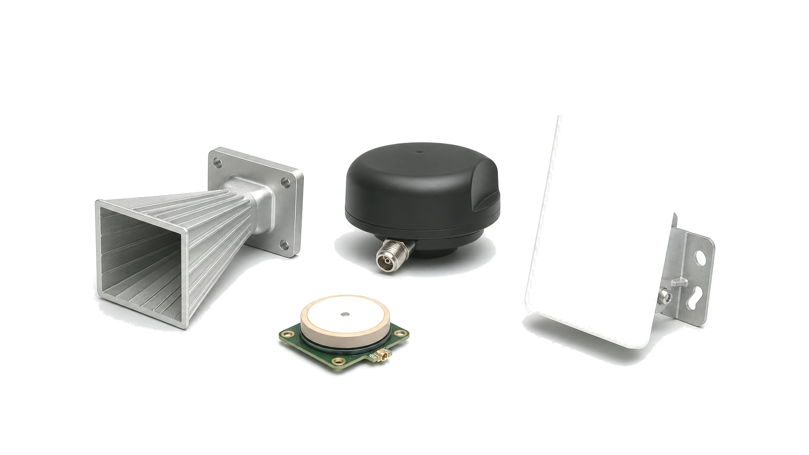
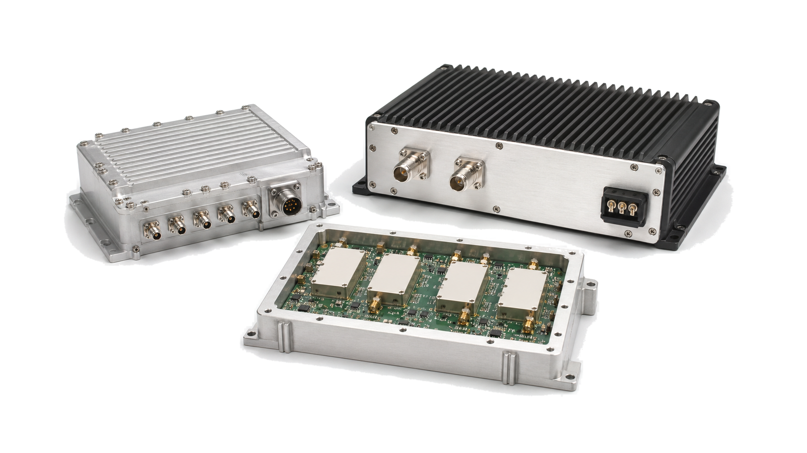
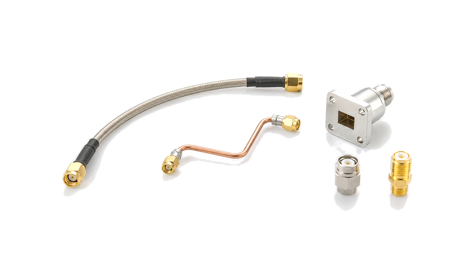
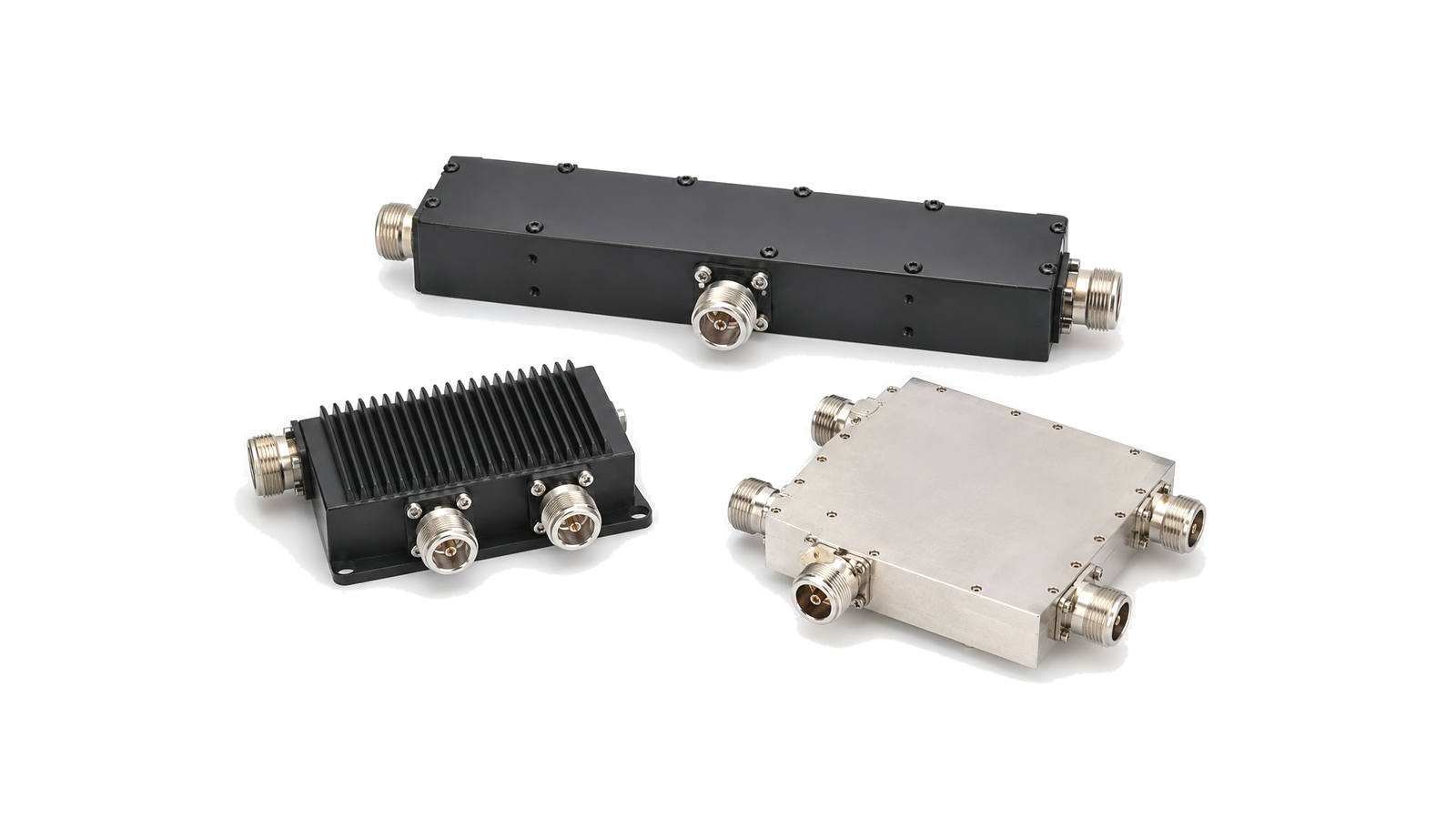
What does an antenna front-end solution include?
It includes the radiating and feed interfaces plus the filtering, switching or duplexing, protection, low-noise receive path, transmit path, coupling, calibration, control, interconnect and thermal-mechanical provisions needed to meet system performance at the antenna reference plane. An antenna front end is not a shopping list of antennas, amplifiers and filters. It is the controlled boundary between free-space performance and the conducted RF chain. A small loss placed before the first receive gain stage raises system noise figure; loss after the power amplifier reduces delivered EIRP and becomes heat; limited transmit-to-receive isolation can compress or damage the receiver. The architecture must therefore be released from one mode table, one set of reference planes and one gain, noise, power and isolation budget.
Engineering decisions covered
- Antenna & Front-End Solutions architecture: defines operating modes, radiating and conducted reference planes, polarization, bands, waveforms and interface ownership
- Antenna & Front-End Solutions design requirements: closes receive sensitivity, blocker tolerance, transmit power, spectral purity, protection and isolation budgets
- Antenna & Front-End Solutions integration: integrates feeds, duplexers, switches, limiters, filters, gain stages, couplers, calibration paths and array control
- Antenna & Front-End Solutions test and verification: verifies conducted paths and over-the-air behavior across scan state, temperature, power, enclosure and production variation
Start with modes and reference planes, not a block diagram
List receive, transmit, standby, calibration, bypass, protection and fault modes, including whether operation is TDD, FDD, simultaneous transmit/receive or multiband. For each mode define the antenna port or radiated aperture, polarization, frequency and instantaneous bandwidth, waveform, duty cycle, peak and average power, desired signal range, blocker environment, scan sector and timing. Mark the conducted reference planes at the antenna, feed, module and transceiver. Without these planes, antenna gain, cable loss, receiver sensitivity and output power can be reported correctly yet assembled into the wrong system budget.
Close the receive budget from the aperture inward
Account for radome, antenna and feed loss, duplexer or switch loss, limiter loss and mismatch before the LNA because these terms directly erode system noise performance. Then cascade LNA gain and noise figure, filter loss, gain-control states and receiver headroom. Check both weak-signal sensitivity and strong-signal behavior: out-of-band blockers, in-band interferers, transmit leakage, intermodulation, compression, recovery time and survivable input. Protection that survives the pulse but remains in compression too long can still make the receiver unusable. State the required noise figure, gain, IIP3, compression, rejection and recovery at the declared antenna plane.
Close transmit power, leakage and thermal budgets together
Translate required field performance into conducted power at the feed using antenna gain, scan loss, polarization loss, radome loss, cable or waveguide loss and mismatch. Budget average and peak output, duty cycle, gain compression, harmonics, spurious emissions and noise. Include coupler, circulator, duplexer, switch and connector power handling under the worst VSWR and load phase, not only a 50-ohm bench load. Every decibel lost after the PA is both missing EIRP and dissipated heat. Confirm transmit leakage into receive paths, isolation between channels and the safe sequence for switching, bias and load states.
Treat array and shared-aperture behavior as an operating state
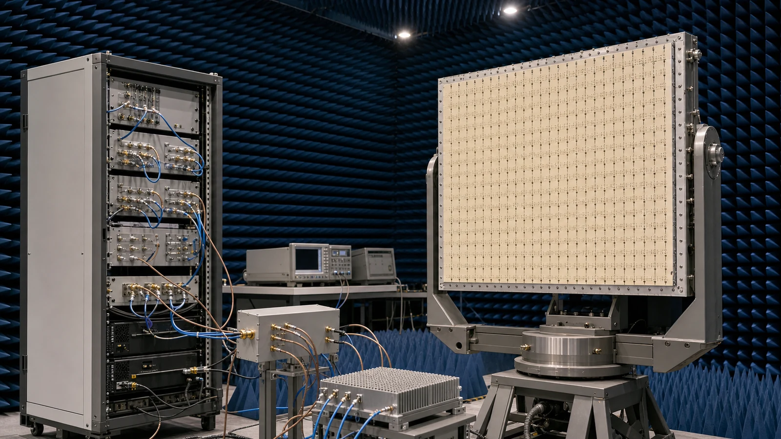
For arrays, element return loss alone does not predict the active impedance, embedded pattern or scan performance once mutual coupling and neighboring excitation are present. Define amplitude and phase command ranges, quantization, channel-to-channel error, timing skew, beam states, polarization and calibration coefficients across frequency and temperature. Shared apertures also require an isolation map between transmit, receive and calibration paths. Provide a controlled calibration injection or observation path where maintainability requires it, but include its loss, directivity and switching repeatability in the same RF budget.
Co-design RF placement with the mechanical and thermal installation
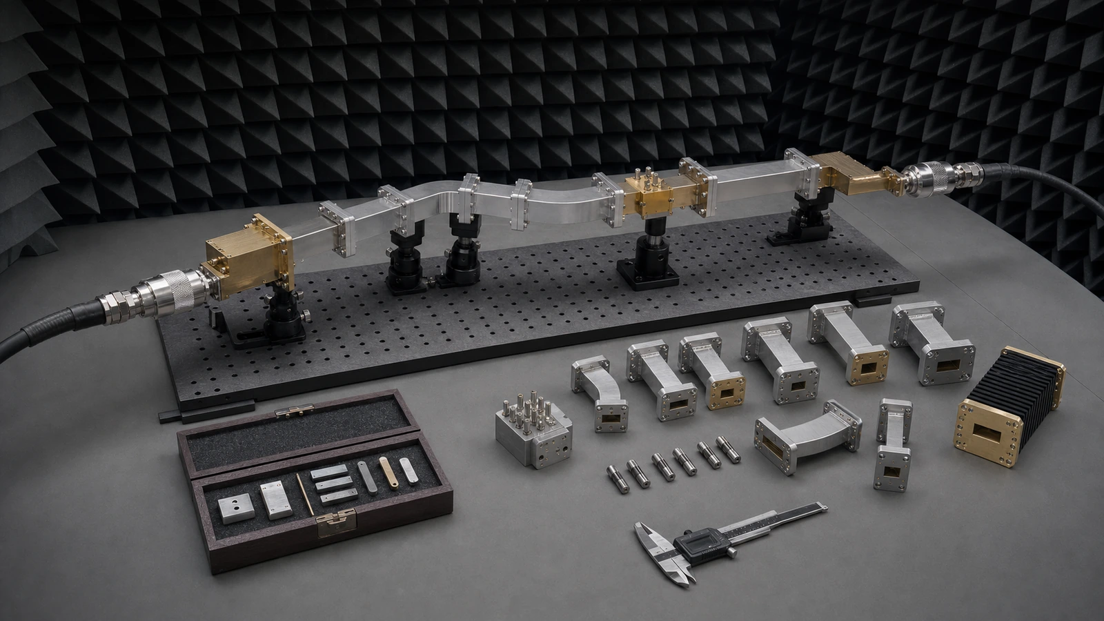
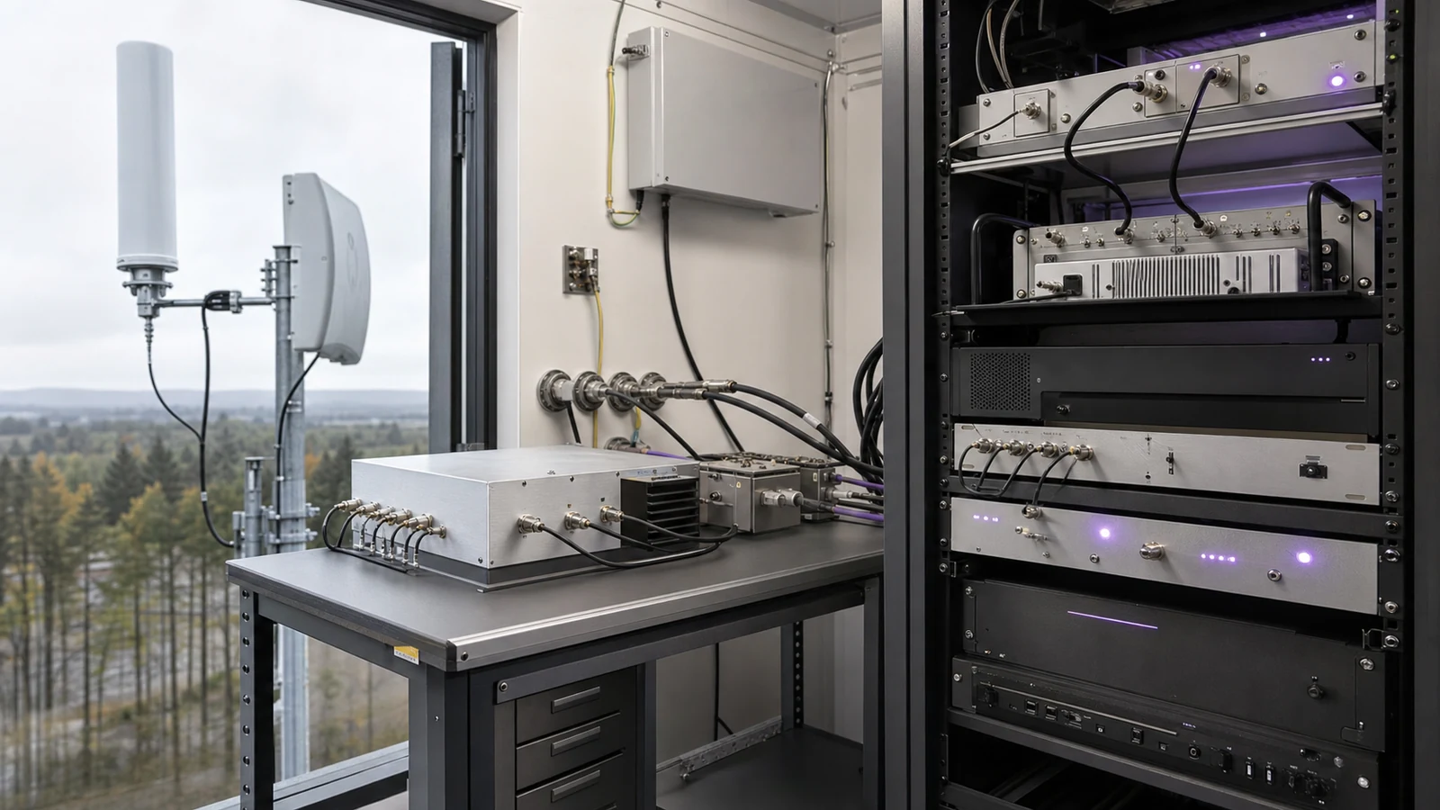
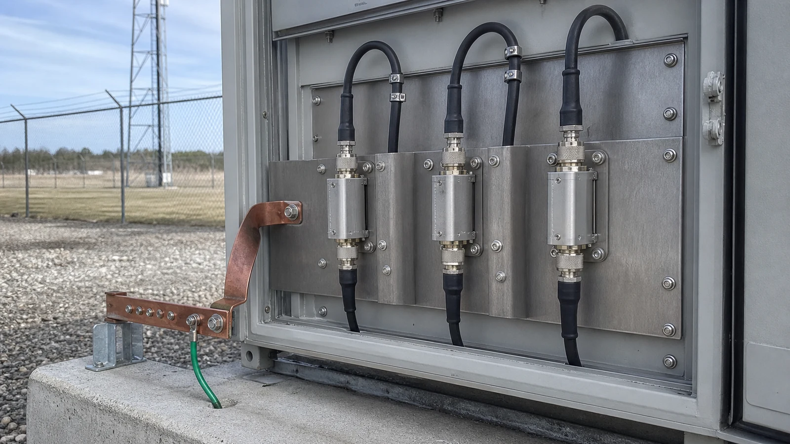
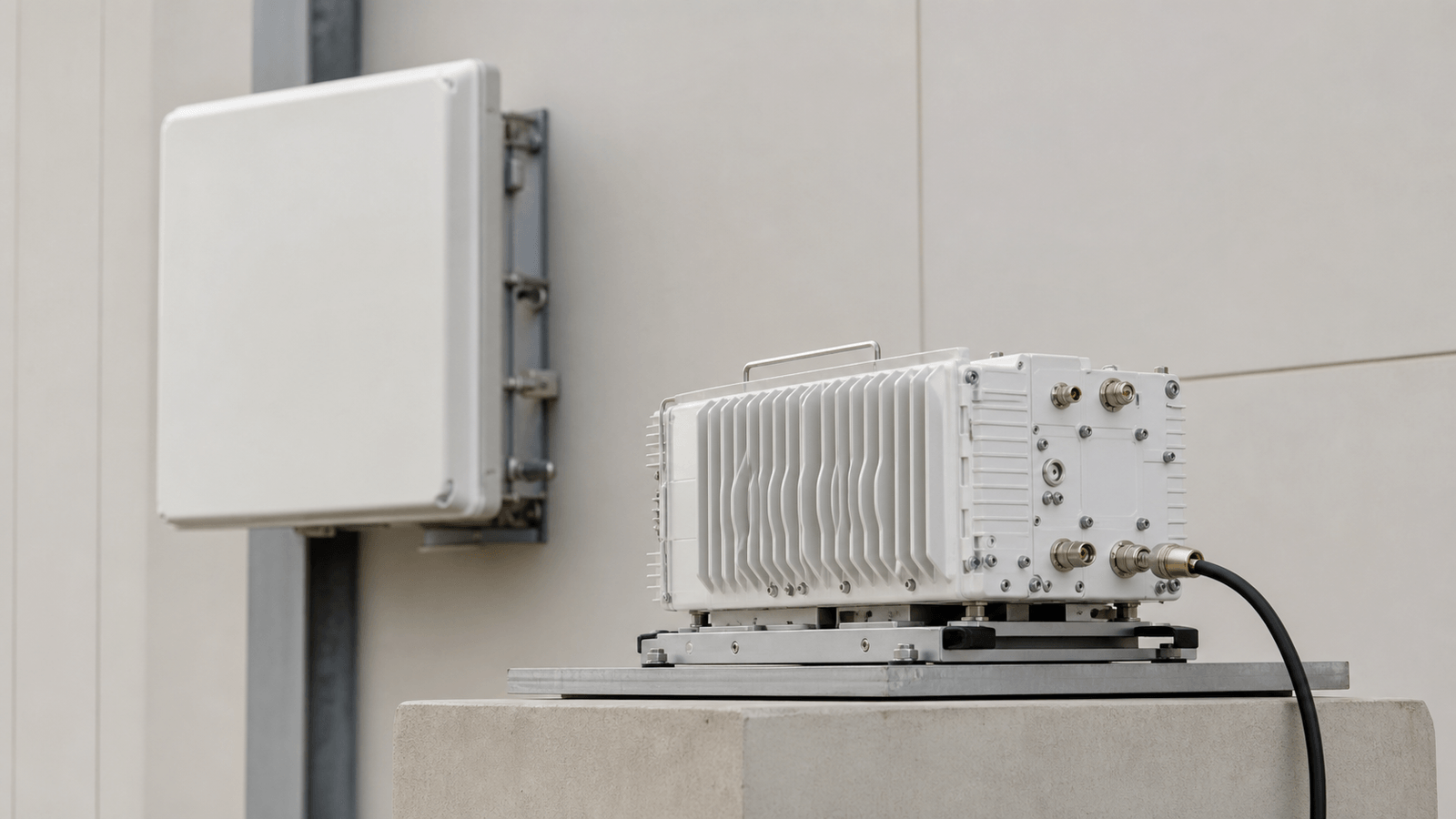
Decide which functions sit at the antenna, behind the radome, in a remote front-end enclosure or at the transceiver. Coaxial cable, waveguide, PCB transitions, connectors, grounding, shielding, sealing, drainage, vibration, bend radius and service access can change the RF result. Keep sensitive receive paths short while separating high-power, noisy digital and bias paths. Define connector datum, torque, cable routing, heat-flow direction, cold-plate interface and allowable temperature gradient. Installation changes that alter feed geometry, ground return or radome spacing require RF re-verification.
Verify conducted performance and the installed radiating system
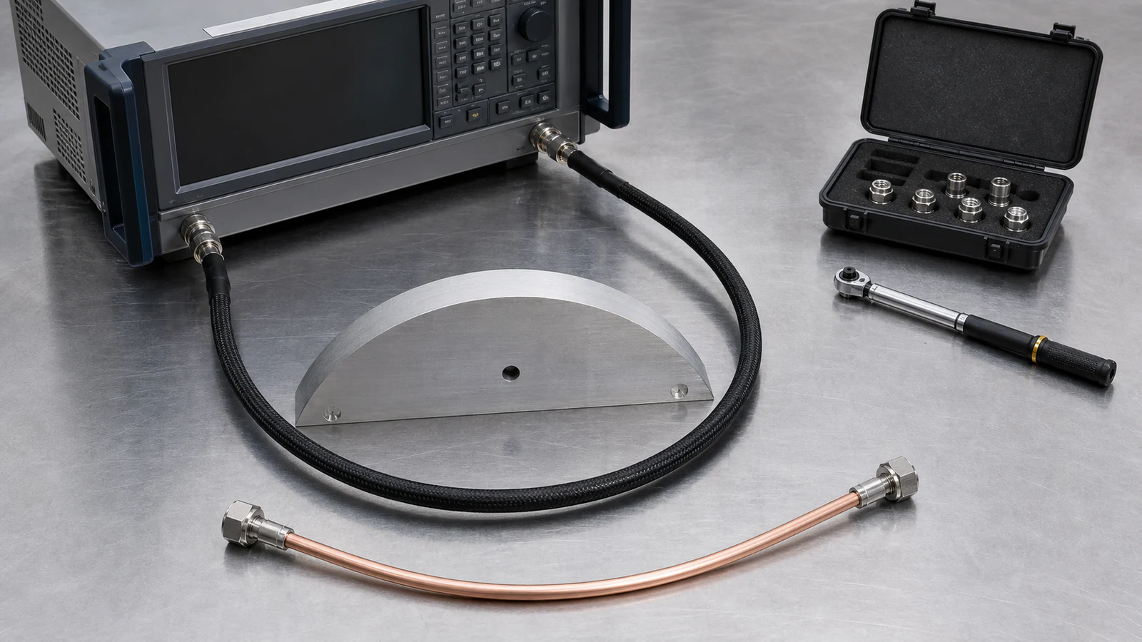
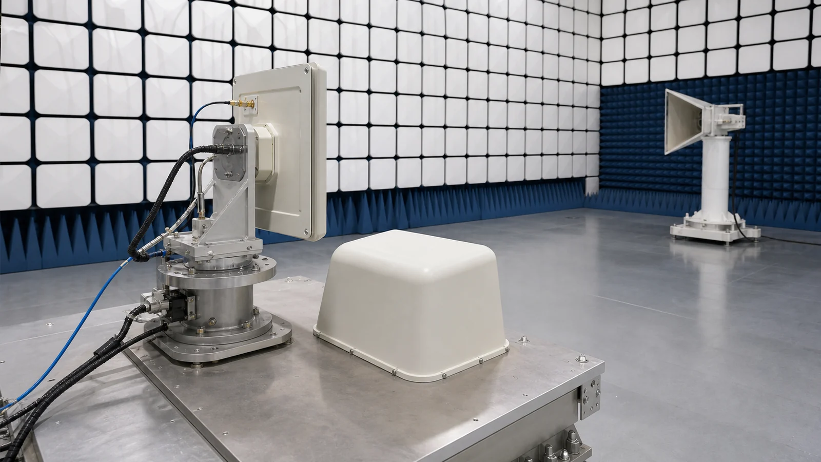
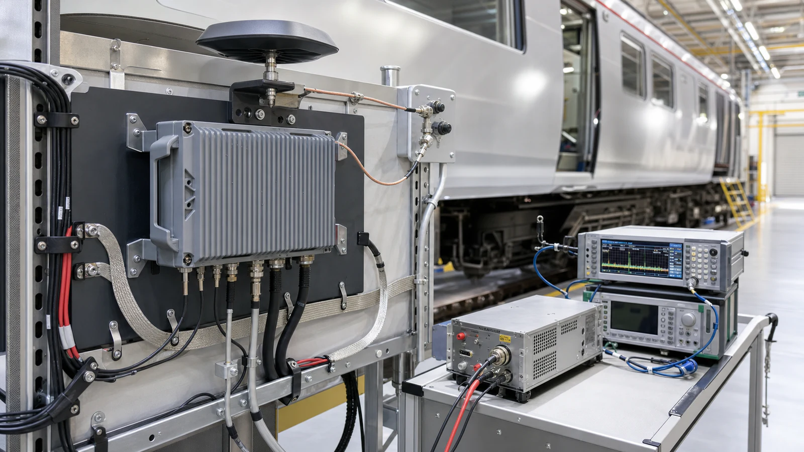
At accessible ports, verify S-parameters, gain and phase, noise figure, compression, linearity, rejection, leakage, switching time, limiter threshold and recovery across every relevant state. For an integrated or active antenna, add calibrated OTA measurements of gain or EIRP, G/T or receive sensitivity, pattern, beam direction, sidelobes, polarization, scan loss and signal quality. Exercise representative beam and frequency states rather than one boresight condition. Correlate chamber, near-field or compact-range results with conducted diagnostics, then repeat critical checks across temperature, power cycling, vibration and production variation. Preserve path corrections, array coefficients, software revision and test geometry with the result.
Antenna front-end architecture release record
| Decision area | Definition required | Verification evidence |
|---|---|---|
| Operating boundary | Modes, bands, waveform, polarization, scan sector and reference planes | Approved mode and interface table |
| Receive path | Pre-LNA loss, NF, gain, blockers, leakage, protection and recovery | Sensitivity, linearity and survivability results |
| Transmit path | Peak/average power, EIRP, loss, isolation, VSWR and thermal load | Power, spectral and load-stress results |
| Array and calibration | Amplitude/phase states, coupling, coefficients and calibration paths | Element/beam correlation and coefficient history |
| Installation | Feed, enclosure, grounding, sealing, cooling and service constraints | Installed OTA result and controlled drawing set |
RFQ inputs for an antenna front-end solution
- Application, deployment environment and regulatory or spectrum constraints
- Frequency bands, bandwidths, duplex method, waveform, duty cycle and timing
- Antenna type, element count, polarization, gain, scan sector and radome
- Receive sensitivity, system NF, blockers, linearity, protection level and recovery
- Transmit peak/average power, EIRP, spectral limits, load mismatch and isolation
- Conducted and radiated reference planes plus connector, cable, waveguide or PCB interfaces
- Filter, duplexer, switch, limiter, LNA, PA, coupler and calibration-path ownership
- Amplitude/phase control, beam states, coefficient storage, BIT and control interfaces
- Envelope, mass, sealing, vibration, grounding, cooling and temperature limits
- Conducted and OTA verification states, production volume, calibration and traceability needs
Solution boundary
The engineering scope defines the system architecture and verification of the path between the radiating aperture and the transceiver. It does not replace a detailed antenna electromagnetic design, assign licensed spectrum, certify regulatory compliance, or guarantee coverage without a propagation model and installed measurements. Product-level ratings and the final safety, environmental and compliance decisions remain with their responsible owners.