What makes an RF test workflow suitable for production acceptance?
It must produce a decision at a named DUT reference plane using a controlled stimulus, characterized measurement path, fit-for-purpose uncertainty, versioned limits and a repeatable sequence whose hardware, software and calibration state are recorded with every result. A fast test is not automatically a production test, and a calibrated instrument does not by itself make the final result traceable. Cables, adapters, fixtures, switch matrices, source leveling, receiver range, DUT state, settling time and correction data all sit between the instrument ports and the quantity being accepted. The workflow must control that complete measurement system while preserving enough evidence to explain a pass, fail, drift or retest.
Engineering work packages covered
- RF Test and Production Workflows architecture: defines measurands, DUT states, reference planes, limits and evidence for development, qualification and production stages
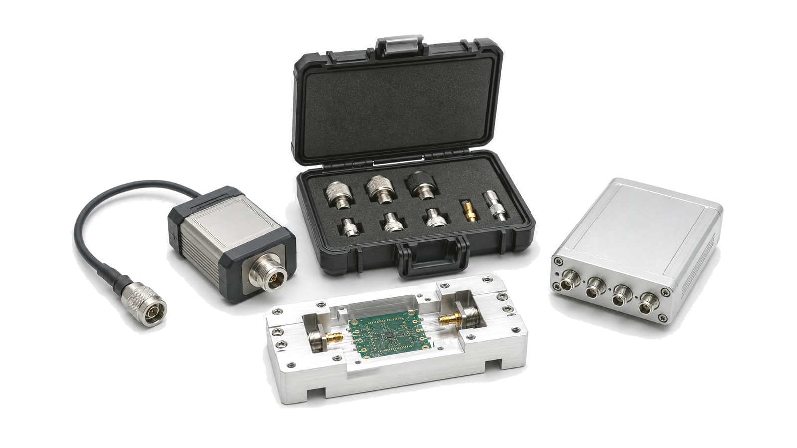
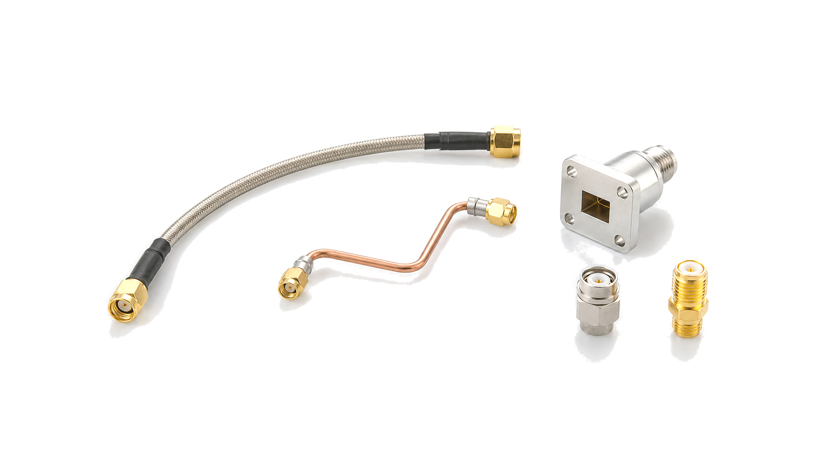
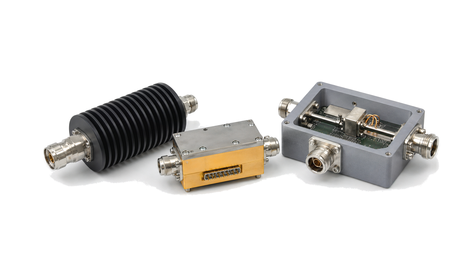
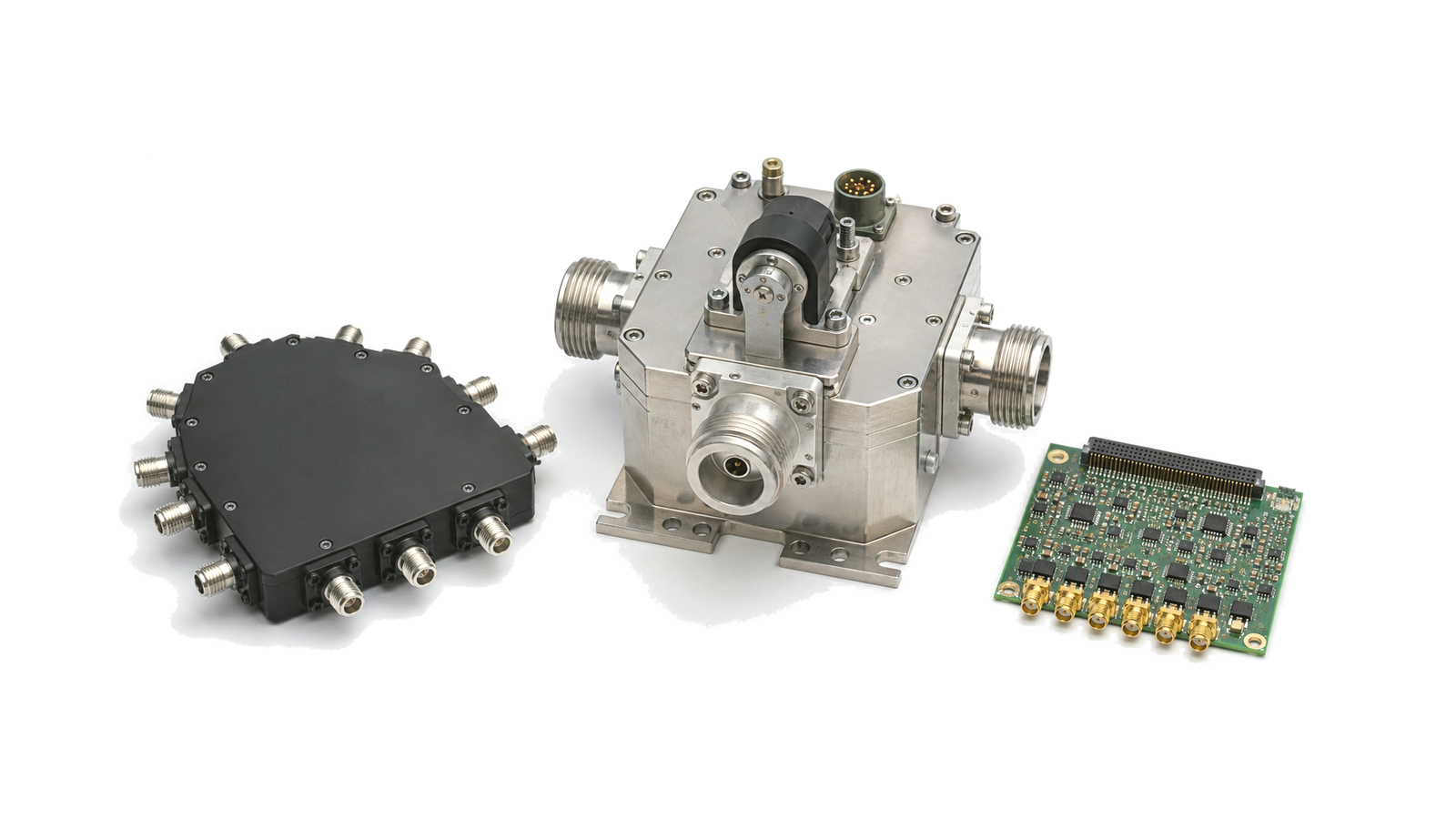
- RF Test and Production Workflows design requirements: characterizes fixtures, cables, adapters, switch paths, loads and mismatch so results refer to the intended DUT plane
- RF Test and Production Workflows integration: combines calibration traceability, uncertainty, guardbanding, check standards and drift monitoring into the acceptance decision
- RF Test and Production Workflows test and verification: controls sequence, automation, correlation, throughput, result genealogy and change release across stations
Define the measurand and the decision before choosing equipment
For every test, state what is being measured, at which DUT port or radiated plane, under which frequency, power, waveform, bias, temperature, load and control state. Separate design characterization, margin exploration, qualification stress and production acceptance. Their stimulus grids and evidence needs differ. The limit table must identify engineering specification, production limit, units, detector or bandwidth settings, averaging, allowed retries and the disposition triggered by a failure. A script that returns a number without this context cannot support a stable acceptance decision.
Move the calibration plane to the DUT deliberately
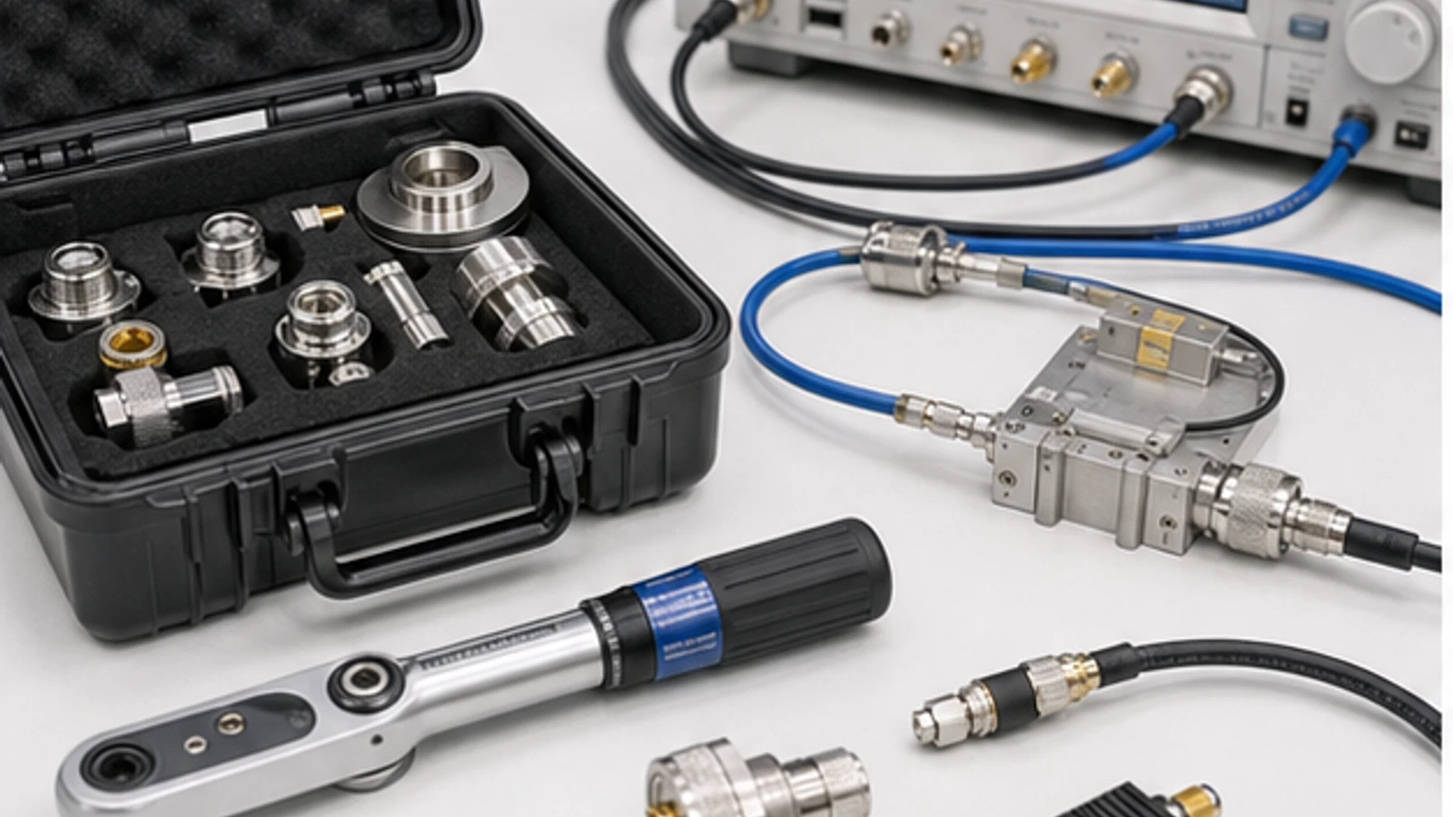
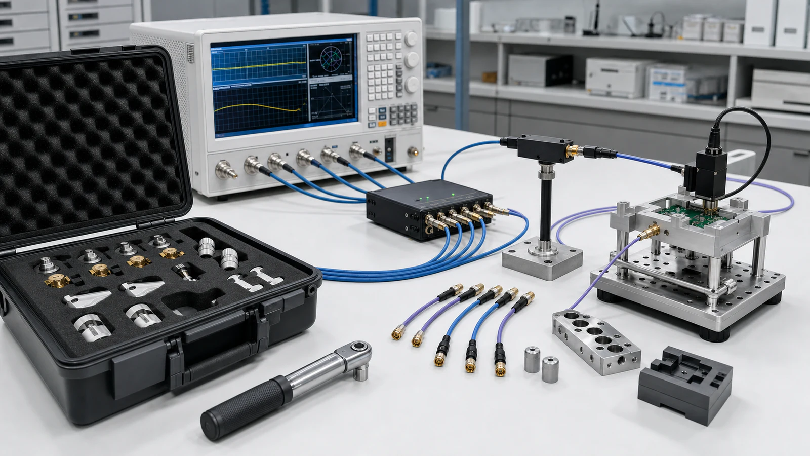
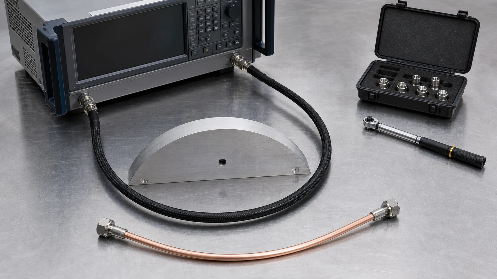
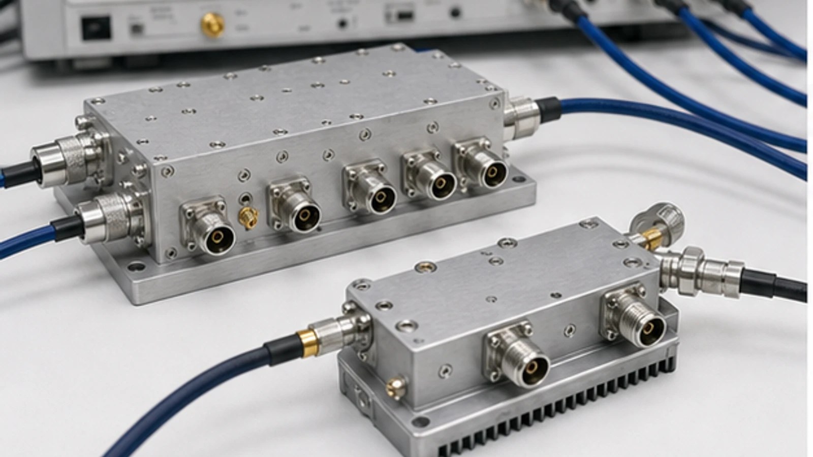
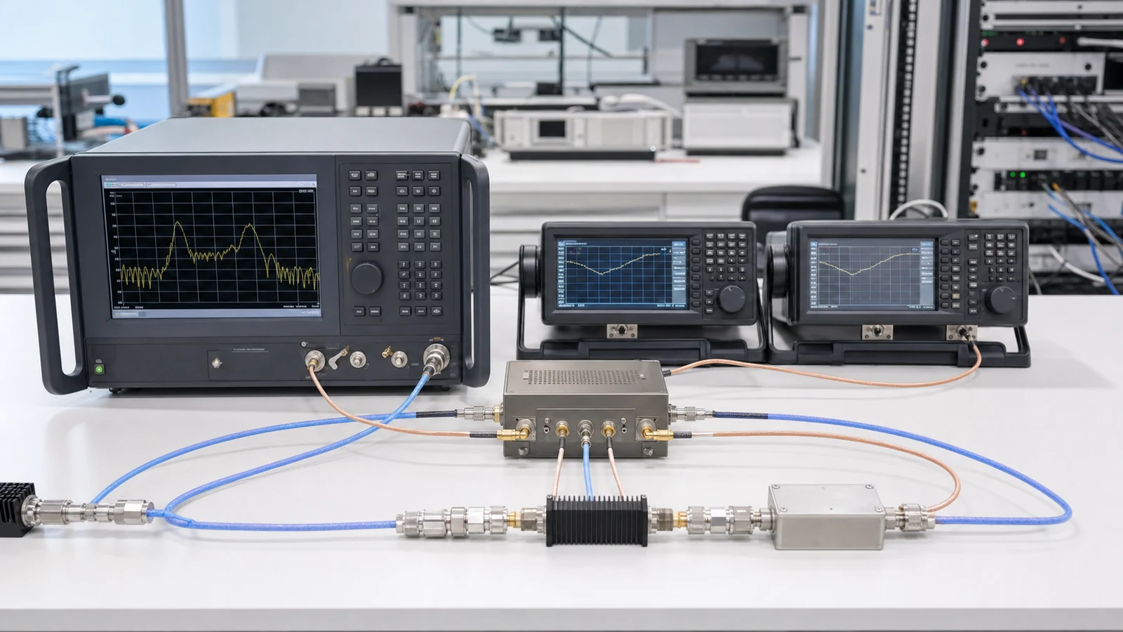
Draw the complete path from source or receiver port through cables, adapters, attenuators, couplers, switches, fixtures and loads to the DUT. Decide whether each element remains inside the measurand, is corrected with scalar loss, is represented by S-parameters, or is removed by de-embedding. Record frequency, power, temperature, switch state and connector torque conditions used to characterize the path. For active tests, mismatch interaction and compression can make a simple loss table insufficient; verify delivered incident power and receiver headroom at the actual DUT state.
Make uncertainty, traceability and guardband part of the limit
A traceable result needs a documented calibration chain and an uncertainty evaluation for the complete result, not only a current instrument certificate. Include reference standard uncertainty, path characterization, connector repeatability, fixture variation, source and receiver linearity, mismatch, drift, environmental effects and algorithm effects where material. Compare combined uncertainty with the decision margin. Apply a declared guardband policy when false accept or false reject risk matters, and keep engineering specification limits separate from the tighter production decision limits.
Automate DUT state and measurement sequence, not just instrument commands
The sequence controls DUT identity, hardware revision, firmware, bias rails, warm-up, mode, frequency, gain state, waveform, trigger, settling, acquisition, overload checks and safe shutdown. Instrument presets alone do not reproduce the test. Use explicit state transitions, timeouts and error handling; verify switch and load states before applying power. Capture raw or diagnostic data for failures while keeping the normal production record compact. Retest rules must distinguish an invalid setup from a valid failing unit and must never hide the first result.
Qualify correlation, repeatability and throughput together
Before release, run representative units across operators, fixtures, stations, days and relevant temperatures. Quantify short-term repeatability, station-to-station bias, fixture contribution and long-term drift for each critical measurand. A golden unit or check standard can monitor the system but cannot replace traceability or uncertainty analysis. Improve throughput by reducing redundant settling, switching and data transfer only after measurement correlation is stable. Parallel paths need independent path corrections and crosstalk checks; one shared correction file is not evidence of equivalent stations.
Preserve result genealogy and control every change
Each accepted result should carry unit serial number, product and hardware revision, test-plan and limit-set revision, station, instrument identity, cable/fixture/switch-path identity, calibration and correction revisions, software version, DUT state, timestamp, operator or automation identity, environmental conditions when relevant, measured values, uncertainty or guardband policy and final disposition. Treat fixture repair, cable replacement, software edits, instrument substitution and limit changes as controlled changes with defined correlation evidence before release.
Minimum release record for an RF production test
| Decision area | Required definition | Release evidence |
|---|---|---|
| Measurand and state | DUT plane, stimulus, mode, bias, load, temperature and units | Approved test definition and state sequence |
| Measurement path | Cable, fixture, switch, load, correction and validity range | Path characterization with revision and uncertainty |
| Limits | Engineering limit, production limit, guardband and retest disposition | Versioned limit table with decision rationale |
| Capability | Repeatability, reproducibility, station bias, drift and throughput | Correlation study and check-standard history |
| Traceability | Unit, station, calibration, software, corrections and raw failure evidence | Searchable result record and controlled change history |
RFQ inputs for a transferable RF test workflow
- Product family, expected variants, annual volume, takt target and station count
- Development, qualification, incoming, in-process, final or customer-acceptance stage
- Measurands, units, frequency and power grids, waveforms and DUT operating states
- Conducted or radiated DUT reference planes and connector or fixture interfaces
- Engineering limits, production limits, guardband policy, retry and failure disposition
- Source and receiver ranges, dynamic range, overload protection, loads and safe states
- Cable, adapter, fixture and switch-path characterization or de-embedding requirements
- Calibration interval, uncertainty target, check standard and drift-monitoring rules
- Automation, DUT control, software ownership, data format and system interfaces
- Correlation sample, station acceptance, maintenance triggers and change-control evidence
Solution boundary
The engineering scope covers the RF measurement path, fixture and switching architecture, calibration and uncertainty plan, automated sequence, acceptance logic and production evidence. It does not define the product's design specification, certify a laboratory, guarantee process capability without representative data, or replace regulatory and safety approvals. Final limits and conformity decisions remain owned by the product, quality and compliance authorities.