
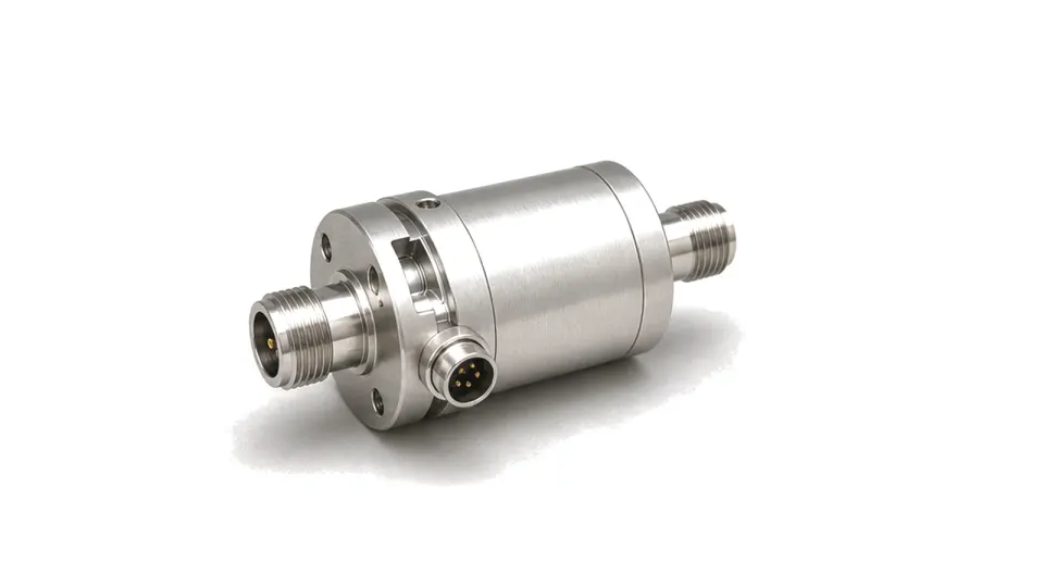
What is an RF rotary joint?
An RF rotary joint is a passive interface that transfers radio-frequency energy between stationary and rotating structures while allowing continuous or limited-angle motion. Its defining performance is not only static loss and match, but how amplitude, phase and channel isolation vary as the shaft rotates.
Define the rotating interface before selecting RF hardware
State whether motion is continuous or oscillatory, the rotor and stator interface orientation, clear bore, envelope, number of RF channels and whether each channel is coaxial, waveguide, contacting or non-contacting. A single-channel test-bench joint, a high-power waveguide channel and a multi-channel radar assembly have different electrical, bearing and packaging boundaries.
Specify RF performance over angle, not at one position
For every channel, define frequency range, insertion loss, return loss or standing-wave ratio, average and peak power, and any pressurization requirement. Then specify peak-to-peak insertion-loss and transmission-phase variation over a full revolution. Multi-channel units also need near-end and far-end isolation plus amplitude and phase tracking between matched channels.
Connect electrical stability to the motion profile
Rotational speed alone does not describe the duty. Provide nominal and maximum speed, acceleration, reversals, dwell pattern, operating hours, target revolutions and allowable starting and running torque. Define axial and radial interface loads, drive coupling, bearing life, shock, vibration and temperature. Cable reaction loads or misalignment can shorten life and change measured RF variation.
Treat service transfer as a separate interface
If the rotating assembly must also carry direct current, low-frequency power, digital data, optical channels or fluids, identify the separate slip ring, optical rotary joint or rotary union and its integration boundary. Do not assume an RF channel can carry service current without affecting power rating, contact life, noise or shielding.
Use dynamic acceptance evidence
Calibrate reference planes to the production interfaces and measure complex scattering parameters at controlled angular increments over the operating band. Repeat under rotation at specified speed to detect contact events, additive phase noise or intermittent loss. Acceptance should report worst-case value and variation over angle, channel isolation, torque, leakage where pressurized, temperature condition, rotation direction and accumulated cycles.
RFQ data for a rotary-joint boundary
- Rotor, stator, axis and mounting drawing
- Continuous or oscillatory motion profile
- Channel count and coaxial or waveguide interfaces
- Frequency, power, pressure and impedance per channel
- Static loss and match plus variation over rotation
- Transmission-phase variation and matched-channel tracking
- Isolation between every relevant channel pair
- Speed, acceleration, torque, loads and required life
- Temperature, shock, vibration, ingress and leakage
- Dynamic test plots, scattering data and acceptance method
Category boundary
This category covers passive RF or microwave rotary joints that transfer electromagnetic energy across a mechanical rotating interface. It excludes fixed adapters, bearings alone, electrical slip rings, fiber-optic rotary joints, fluid rotary unions, cable reels and complete antenna pedestals unless those functions are intentionally integrated and separately specified.