
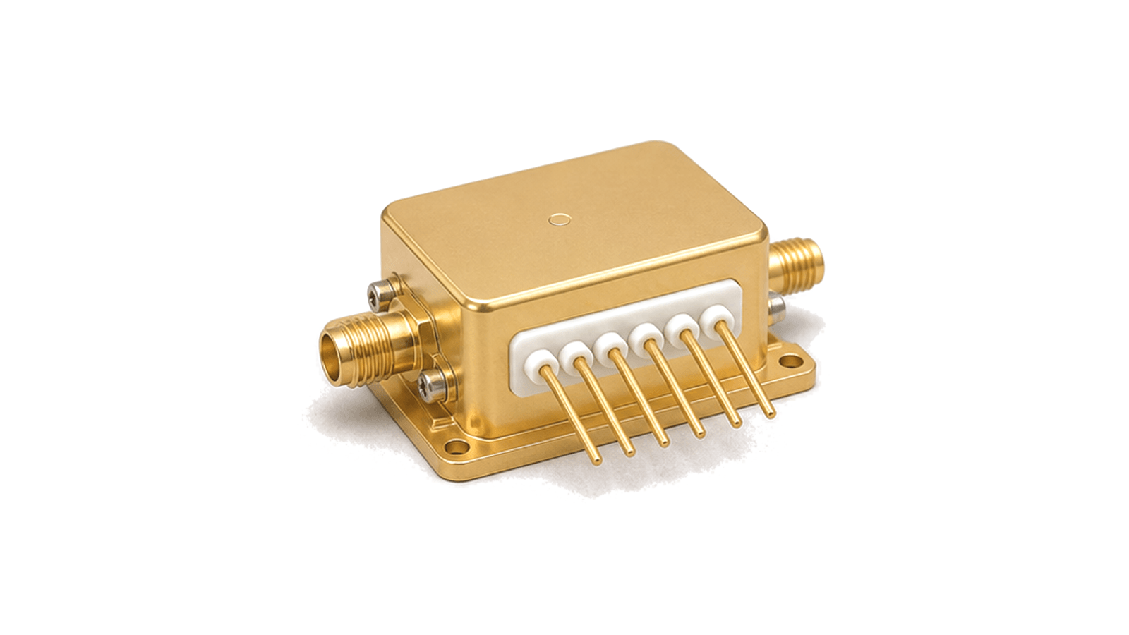

What must be defined before a hermetic RF package can be qualified?
Define the RF reference planes, cavity and feedthrough geometry, material and thermal stack, sealing process, internal atmosphere and the exact gross- and fine-leak acceptance method before qualification begins. A hermetic RF package is more than a closed metal box. It is an engineered boundary around an MMIC, hybrid or microwave circuit, with RF, bias and control conductors passing through a metal, ceramic or glass-sealed structure while the base carries heat and the lid completes the seal. The package must preserve both the internal environment and the intended electromagnetic reference planes after assembly. A weather-resistant enclosure, removable RF connector or non-hermetic shield can is not equivalent.
Co-design the RF transition, cavity and ground path
Set the operating band, port count, impedance and required return loss, insertion loss, isolation and phase behavior at named internal and external reference planes. Feedthrough diameter, dielectric, pin length, launch geometry, via or wall grounding and the transition into microstrip, stripline, coaxial or waveguide structures determine package parasitics. Check cavity dimensions and lid height for resonances, coupling and field concentration rather than treating the housing as electrically neutral. Bias and control feedthroughs also need filtering, insulation and spacing appropriate to the applied voltage and spectrum.
Match materials, sealing process and thermal path
Select metal, ceramic, glass, braze, plating, die attach and lid material as one stack. Coefficients of thermal expansion, process temperature, weld or solder compatibility and surface finish affect feedthrough stress, bondability and seal integrity. Define the heat source, allowable junction or base temperature, heat-spreader geometry, mounting flatness and external sink interface. Record whether the cavity is evacuated, dry-gas filled or controlled by another approved process, together with bakeout, cleaning, getter and rework rules where applicable.
Qualify hermeticity and RF performance after stress
Hermeticity is an acceptance result, not a material label. State the applicable leak-test method, tracer, pressure and dwell conditions, package-volume correction, gross- and fine-leak limits and the point in the assembly flow when testing occurs. Repeat seal verification after the required temperature cycling, mechanical shock, vibration or pressure exposure. Then measure the completed RF transitions over band, confirm electrical isolation and continuity, inspect welds, brazes, plating and feedthroughs, and correlate thermal performance with the final mounting condition.
- Operating band, port topology and internal and external RF reference planes
- Feedthrough dielectric, pin geometry, launch, grounding and cavity resonance limits
- Housing, ceramic or glass, braze, plating, lid and CTE compatibility
- Power dissipation, heat spreader, base flatness and external thermal interface
- Internal atmosphere, cleaning, bakeout, sealing and permitted rework flow
- Gross/fine leak, environmental stress, RF and thermal acceptance sequence
Evidence and category boundary
The hermetic claim requires a documented test method and acceptance limit for the final sealed assembly. This category covers sealed RF package bodies, lids, headers and integrated feedthrough transitions; it excludes ordinary shielded enclosures, detachable coaxial connector selection, stand-alone hermetic penetrators and complete populated RF modules when the package is not the purchasing task.