
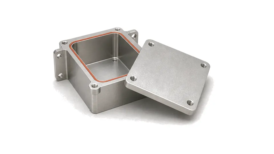
How should an RF shielding enclosure be specified and verified?
Specify the enclosure from the real interference path and required attenuation, then verify the completed assembly with every seam, aperture, penetration and access panel installed. RF shielding is a system property, not a material label. A conductive wall can perform well as a coupon while a long slot, poorly bonded lid, cable shield termination, vent or display opening dominates leakage in the finished assembly. The required design therefore begins with the emitter, protected circuit, frequency range, separation and field geometry, and ends with a repeatable test of the actual enclosure configuration.
Define the coupling problem before choosing the enclosure
Identify the source and victim, operating and transient frequencies, required attenuation at the protected node and whether the exposure is predominantly electric field, magnetic field or far-field plane wave. Near-field shielding depends strongly on distance and source geometry; low-frequency magnetic fields may require permeability as well as conductivity. Record internal cavity dimensions, likely resonances, heat sources, antenna or high-current regions and every cable or mechanical path that crosses the boundary. A single broadband shielding number without a method, frequency and geometry is not an acceptance requirement.
Control seams, apertures, penetrations and electrical bonds
Preserve a low-impedance surface-current path across lids, doors, panels and partitions. Specify contact finish, gasket type, compression range, flange stiffness, fastener spacing, corrosion compatibility and the number of service cycles. Treat vents, displays, shafts and slots by their largest effective dimension and orientation, not only by open area. Define how coaxial shields, connectors, power, control and data conductors cross the wall; an unbonded cable shield or unfiltered conductor can bypass the enclosure. Grounding architecture, internal partitions and absorber use must follow the measured coupling path rather than being added as decoration.
Verify the completed enclosure under installed conditions
Agree the shielding-effectiveness method, source and receive antenna or probe, reference geometry, frequency sweep, calibration and system dynamic range before testing. Measure the fully assembled enclosure with production fasteners, gaskets, vents, connectors, cable terminations and access covers. Compare the closed result with a documented reference, scan seams and penetrations to locate dominant leakage, and repeat critical points after open-close cycles, vibration, temperature or corrosion exposure when those conditions apply. Bench near-field scans are valuable for diagnosis but do not replace the specified compliance or qualification measurement.
- Emitter, protected circuit, frequency range and required attenuation
- Electric, magnetic, near-field or far-field exposure and test geometry
- Enclosure material, thickness, cavity dimensions and thermal constraints
- Seams, gaskets, finishes, fasteners, apertures, vents and service cycles
- Connector, cable, power, control and display penetration treatment
- Reference measurement, dynamic range, leakage scan and post-stress retest
Category boundary
This category covers RF shield boxes, conductive enclosure bodies, lids, partitions, seams, gaskets and shielding treatments whose purchasing task is field containment around an assembly. Hermetic RF packages, stand-alone absorbers, feedthrough filters, RF windows and radomes, and complete functional RF modules remain separate categories because shielding is not their sole selection boundary.