
How should an RF connector be specified for an installed signal path?
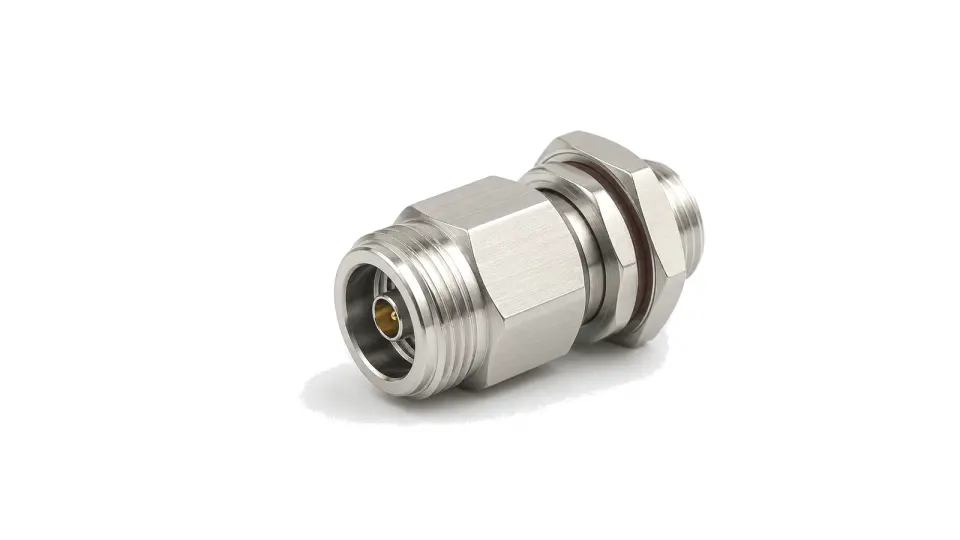
Specify the connector from the required reference-plane performance and mechanical interface, then verify the completed cable, panel or enclosure transition rather than accepting the connector family name alone. This category covers detachable coaxial connector series and cable, bulkhead and chassis interfaces used to carry RF or microwave signals. It is the parent selection page for connector families such as SMA, N, TNC, 2.92 mm, 2.4 mm and SMP. A familiar outline does not prove electrical interchangeability, and a pair that can be physically mated may still have a lower usable frequency, different torque requirement or unacceptable repeatability.
Define the electrical and mechanical interface together
Start with 50 or 75 ohm impedance, highest operating and test frequency, required return loss or VSWR, insertion loss and the exact male, female, plug, jack or genderless interface. Record the governing interface standard, coupling method, panel or cable geometry and mating compatibility. Do not infer compatibility from thread size or appearance. Precision interfaces may be mechanically related to another family while their guaranteed frequency range, pin geometry or allowable mating combinations remain different.
Check power, installation and service conditions
Connector power capability depends on frequency, continuous and peak power, duty cycle, mismatch, temperature, altitude and heat flow through the cable and mounting surface. Add environmental sealing, vibration, corrosion resistance, shielding and passive-intermodulation requirements only where the installed system needs them. Select the cable attachment, flange or bulkhead style, panel thickness, strain relief, tool access and service life at the same time; otherwise a sound RF interface can fail during assembly or maintenance.
Verify the assembled reference plane
Calibrate the measurement to the agreed connector reference plane and test the actual cable, launch, panel or enclosure transition over the operating band. Record return loss or S11, insertion loss or S21, phase when relevant and repeatability after controlled disconnect and reconnect cycles. Use the specified torque tool, inspect mating surfaces and center conductors, confirm pin depth or gauge limits for precision interfaces, and reject contamination or mechanical damage before testing. Measure PIM only with a suitable low-PIM setup and system-level limit.
- Impedance, operating band and highest verification frequency
- Exact interface standard, mating pair, gender and coupling method
- Continuous and peak power, duty cycle, mismatch, altitude and temperature
- Cable termination, panel thickness, mounting, sealing and strain relief
- Return loss, insertion loss, phase, shielding or PIM acceptance limits
- Torque, inspection, mating-cycle and installed-path test procedure
Category boundary
This category supports broad selection of detachable coaxial RF connector series and cable or chassis interfaces. PCB launches and board-to-board geometry, hermetic feedthroughs, stand-alone adapters and complete cable assemblies are separate selection tasks because their dominant reference planes and failure mechanisms are different.