LCRF

Privacy preferences

Choose optional purposes independently. You can change or withdraw your choice at any time from the footer.

Strictly necessary

Required for security, session functions and storing your privacy choice.

Always active
Preferences

Remembers optional display or language settings when these features are enabled.

Analytics

Uses first-party visitor and session identifiers to measure pages, referrals and inquiry interactions.

Marketing

Allows marketing measurement or third-party advertising technologies if they are introduced in the future.

Antenna Feed & Matching

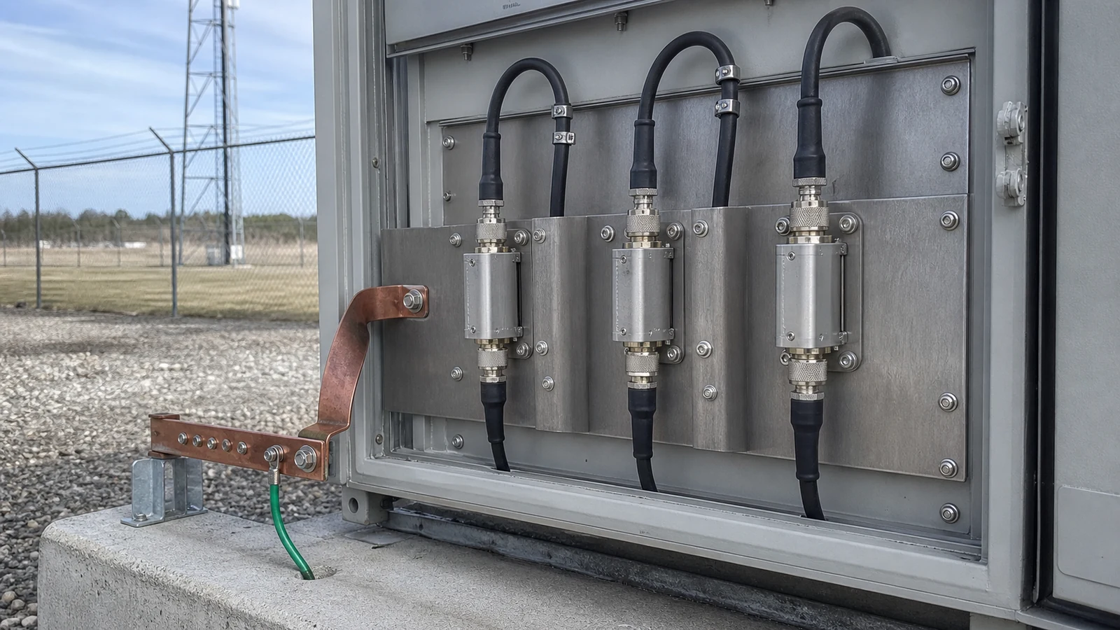
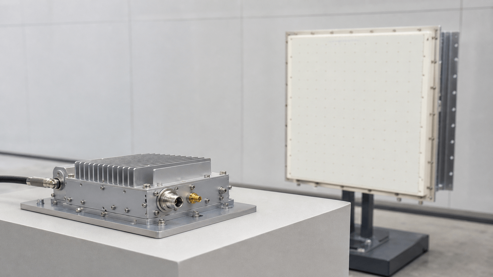
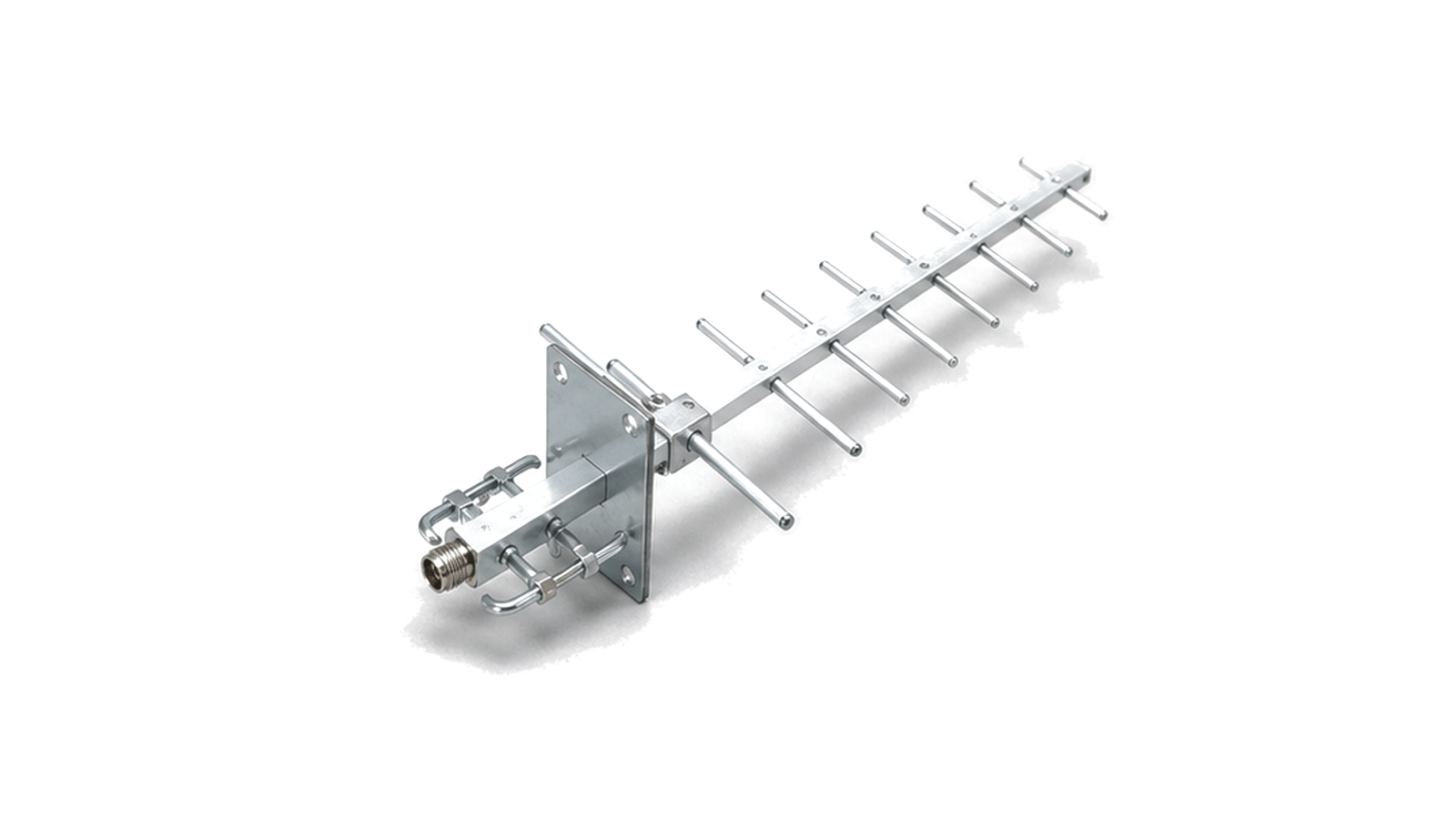
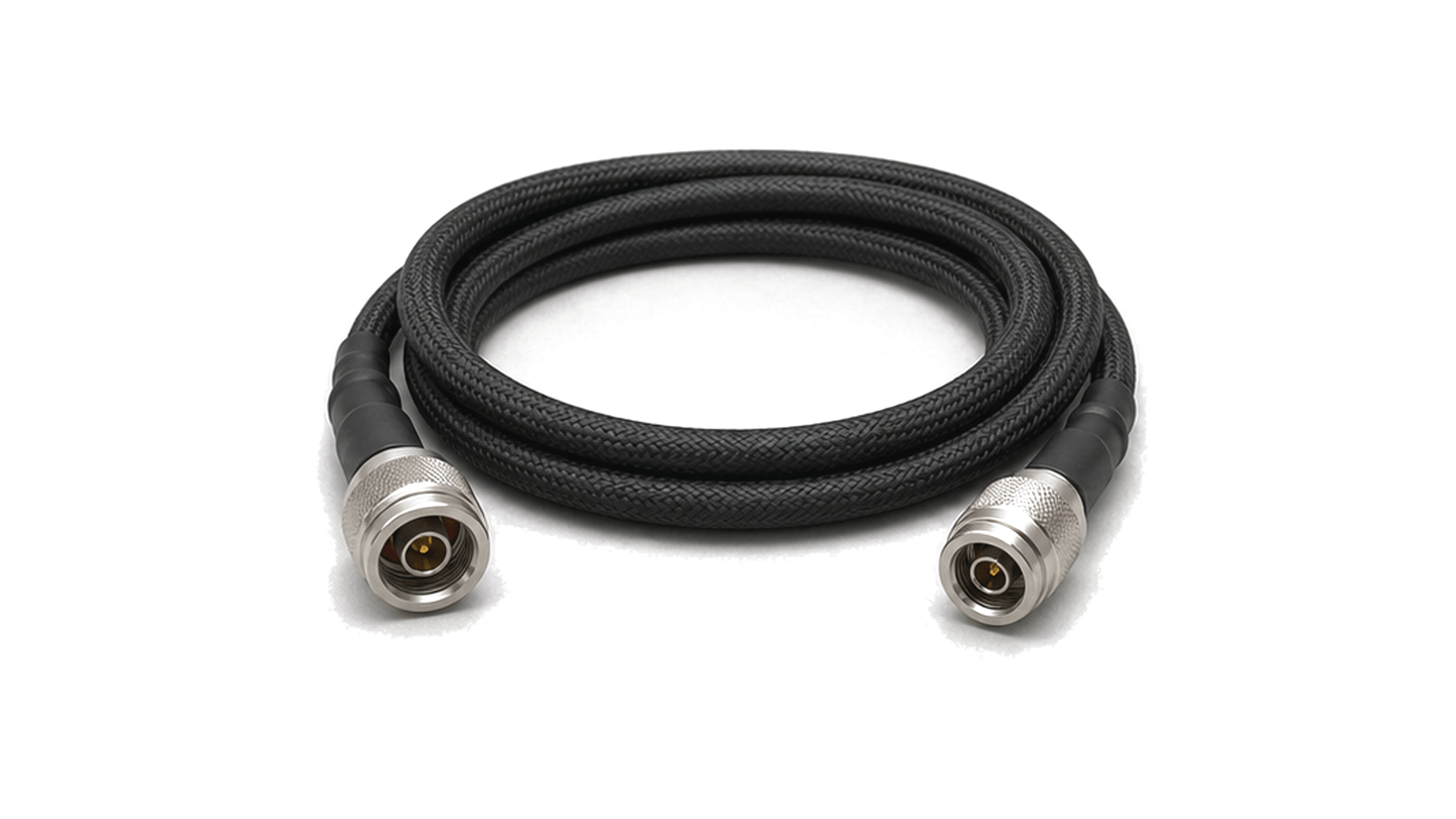
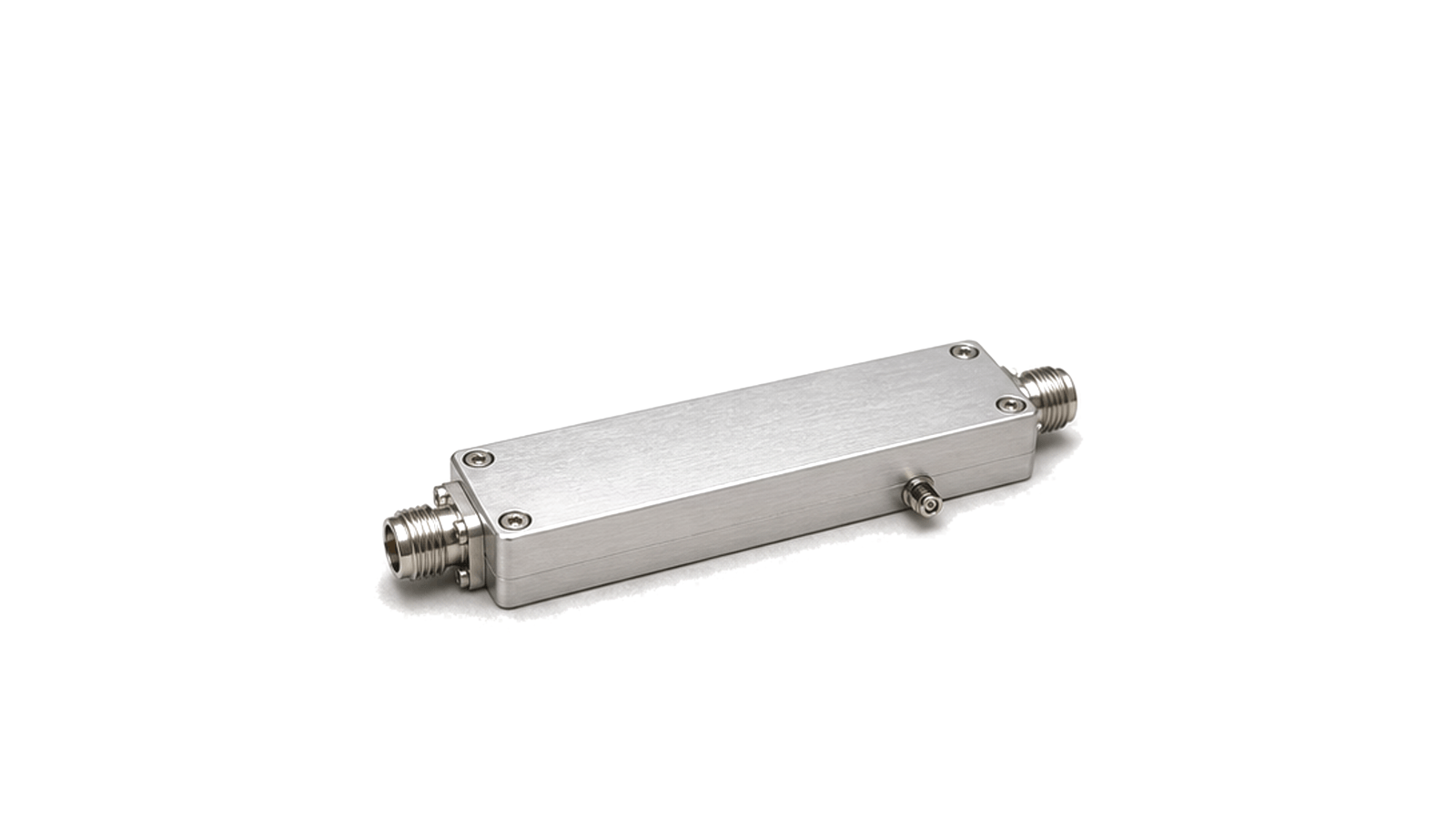
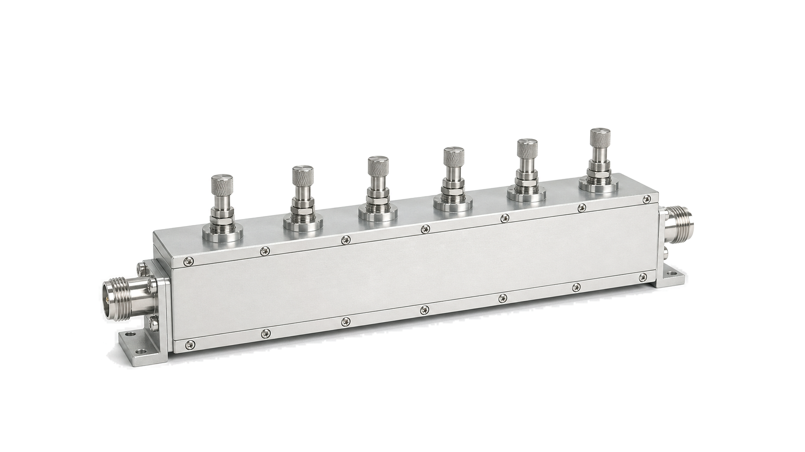
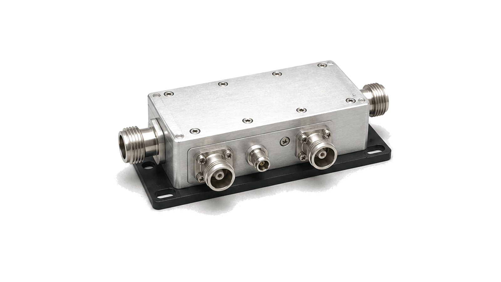
Antenna feed and matching hardware carries RF energy between the transceiver and radiating element while managing impedance, loss, coupling and mechanical fit. It applies to coaxial, waveguide and custom feed paths.

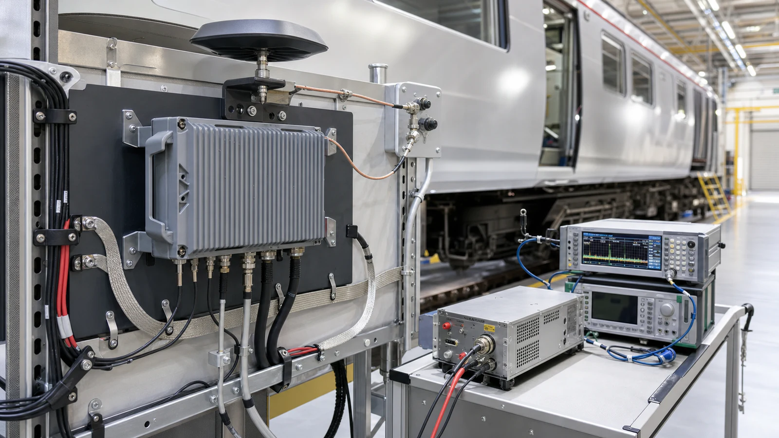
Antenna Feed & Matching RF solution visual

Antenna Feed & Matching

Antenna feed and matching hardware carries RF energy between the transceiver, amplifier or receiver and the radiating element. The path manages impedance, insertion loss, coupling and mechanical fit.

Feed boundary

The boundary can include coaxial cables, adapters, couplers, filters, matching sections, waveguide transitions and antenna-port hardware.

Interface data

Relevant data includes operating band, impedance, VSWR, insertion loss, coupling factor, connector or flange type, bend radius, power rating and installation geometry.

Define the installed radiation requirement before comparing antennas

Antenna Feed & Matching architecture
Freeze continuous band coverage and the conducted reference plane List every transmit and receive range, guard band and operating state as continuous intervals. A nominal center frequency does not reveal a notch, split band or scan-state limitation....
Antenna Feed & Matching design requirements
Make the platform, radome and nearby structures part of the antenna configuration Ground plane size, mast, vehicle roof, fuselage, enclosure, cable routing, fasteners and nearby conductive equipment can alter match, pattern, efficiency, phase center and cross-polarization....
Antenna Feed & Matching integration
Translate the real waveform and environment into accepted port stress State CW, average and peak power, pulse width, duty cycle, modulation crest factor, number of simultaneous carriers, source and load mismatch, reverse power and temperature at each port. A single power rating cannot represent heating, electric-field peaks and breakdown risk under every waveform....
Antenna Feed & Matching test and verification
Design the measurement and evidence package before purchase Conducted tests can establish port match, isolation and feed-network behavior, but radiated gain and pattern require an over-the-air method. State whether substitution gain, comparison gain, near-field transformation, compact-range or far-field measurement is acceptable....

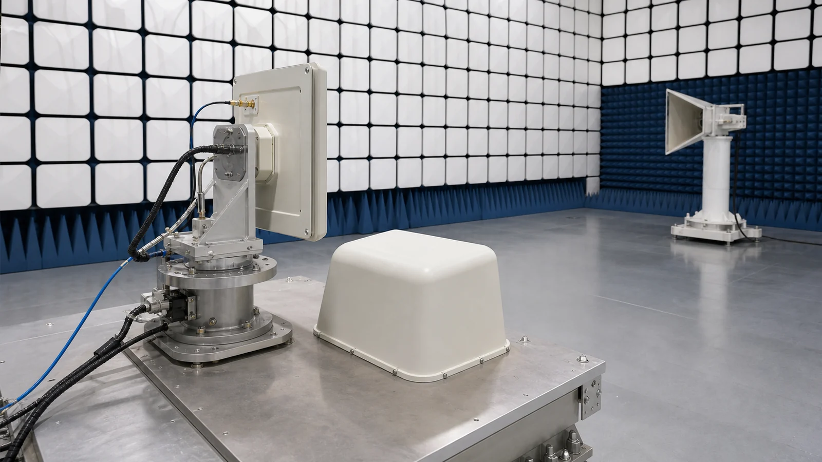
How to Select an RF Antenna: Frequency, Gain, Pattern, Polarization, Match, Power and Installation

A practical antenna-selection method that turns operating band, angular coverage, gain pattern, polarization, port match, waveform power, mounting environment and measurement evidence into an RFQ and acceptance plan.
RF Antenna Selection and Installation Guide

Articles

FAQ

Why can an installed antenna pattern differ from the free-space data sheet?

Ground planes, structures, cables, radomes and mounting tolerances change current distribution and scattering, which can alter match, gain, pattern, polarization and phase center.

What must be specified for a mobile-platform RF antenna and coax installation?

Define the installed antenna boundary, body or ground plane, feedthrough, protection, complete coax route, reference planes, mechanical support and replacement limits.

How are antenna VSWR, return loss, reflection coefficient and mismatch loss related?

VSWR, return loss and reflection coefficient express port mismatch; mismatch loss quantifies the accepted-power penalty, but none proves radiation efficiency or pattern.

How should linear, circular, axial-ratio and cross-polarization requirements be specified?

Define linear orientation or circular sense, the viewing and coordinate convention, axial ratio, cross-polar limits and the frequency and angular region where they apply.

What is the difference between antenna gain, directivity, beamwidth and sidelobes?

Directivity describes angular concentration, gain includes dissipative efficiency, beamwidth describes main-beam extent and sidelobes describe radiation outside that beam.

How are environmental and EMC tests tailored for rail, maritime, road and airborne RF hardware?

Derive test category, severity, axes, harness, operating modes and pass criteria from the exact installation rather than treating a platform standard as a universal certificate.

How should vehicle power transients, returns and chassis bonding be specified for RF hardware?

Specify the voltage and transient at the equipment terminals with source impedance and harness state, then control returns, shields and chassis bonds as separate verified paths.

Which RF and impulse ratings must be compared for a coaxial surge protector?

Frequency, match, loss, power, PIM and DC behavior must be checked alongside impulse waveform, current, sparkover, residual voltage and follow-current limits.

Engineering inquiry

Share your RF requirement

Share the product, operating requirements and project context. Our engineering team will route your request to the right specialist.

AttachmentsAttach drawings, BOMs, specifications or test files. Up to 5 files, 10 MB each and 25 MB total.
or drag and dropPDF, DOCX, XLSX, CSV, TXT, JPG, PNG, S1P and S2P
Typically reviewed within one business dayProject information is handled confidentially