
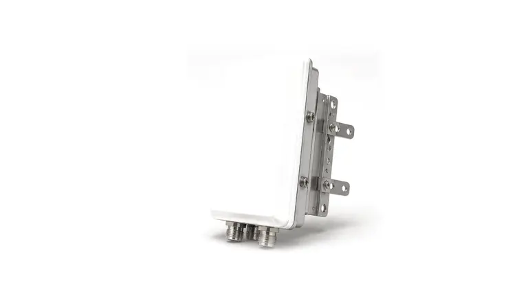
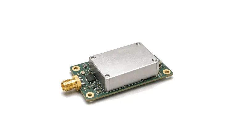
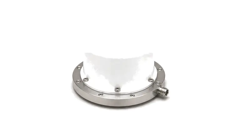
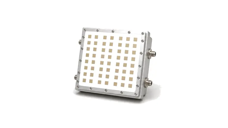
What must be defined before selecting an antenna or radiating front end?
Define the installed reference plane, required coverage volume, polarization, RF and power budgets, mechanical environment and acceptance method before choosing an antenna type. A catalog gain value does not describe how an antenna will behave on the final platform. Feed loss, mismatch, radome material, ground plane, nearby structures, cable routing and mounting tolerance can change realized gain, beam direction, sidelobes, polarization purity and efficiency. The useful specification therefore combines RF data with installed geometry and evidence measured at the states the system will actually use.
Start with mission geometry and the radiating boundary
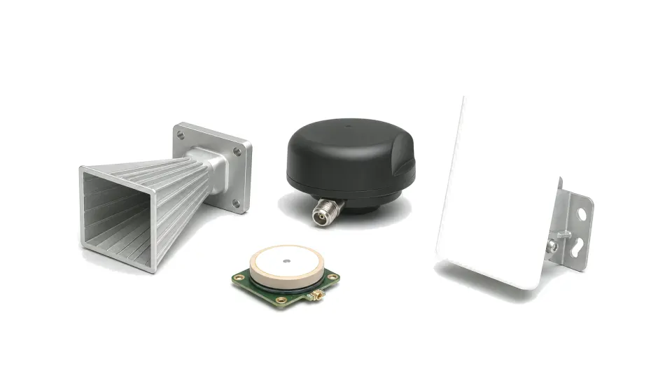
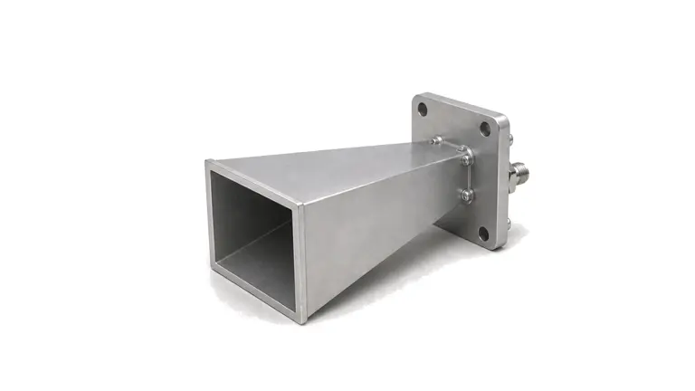
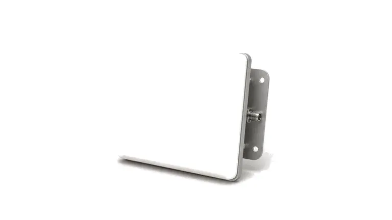
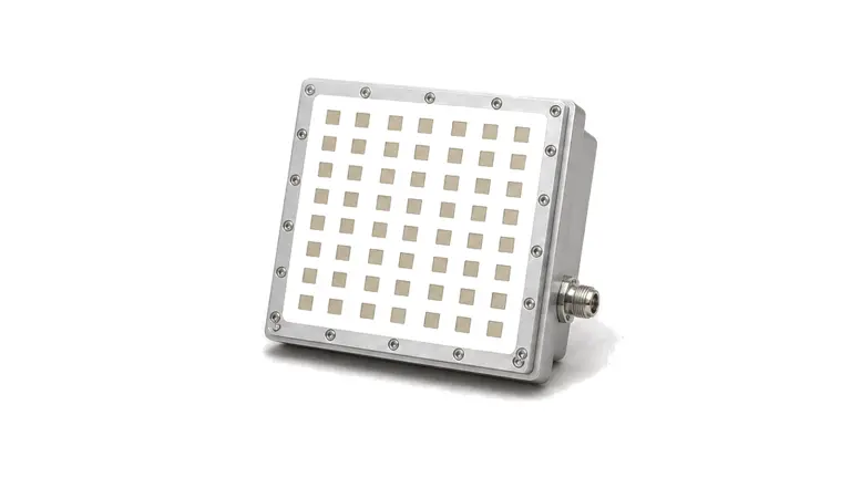
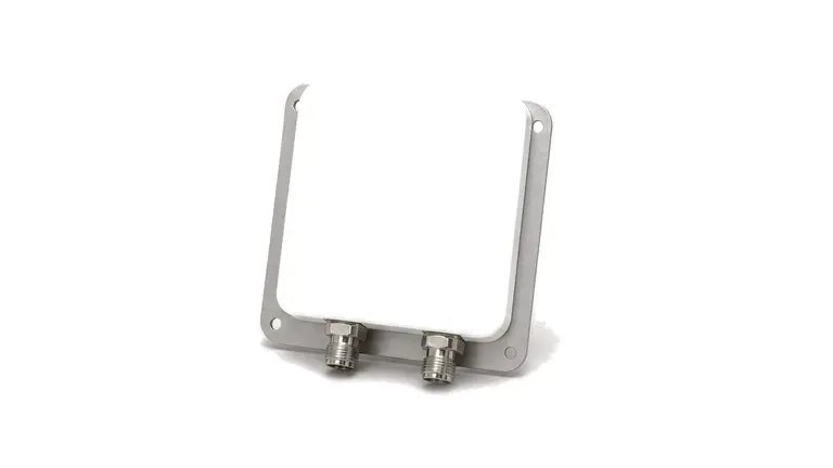
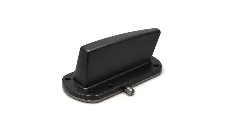
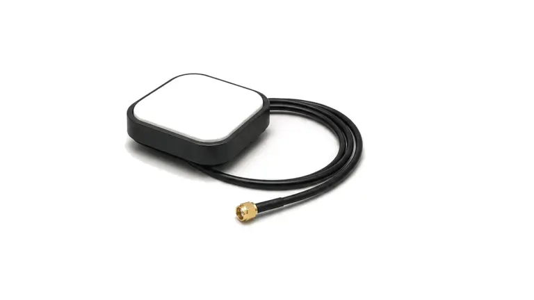
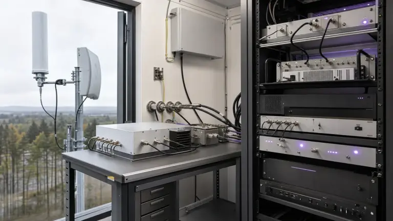
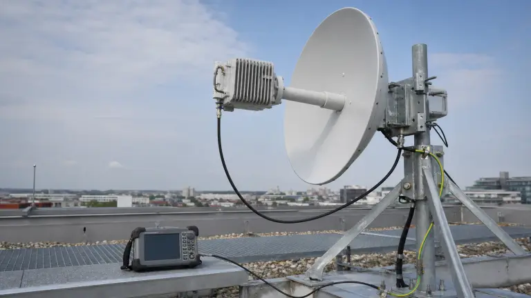
State whether the link is fixed, mobile, airborne, naval or indoor; transmit, receive or duplex; line-of-sight, area coverage, tracking or direction finding. Define the required azimuth and elevation coverage, minimum gain or field strength over that volume, range assumptions, target or user motion and allowed exclusion zones. Freeze the antenna reference plane, available aperture, ground plane, keep-out region, radome, mast or vehicle position and nearby conductive or dielectric structures. Select omnidirectional, sector, horn, reflector, helical, panel or array architecture from the required pattern and polarization rather than from the product name alone.
Close the RF, polarization and linearity budgets
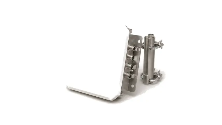
Specify every operating band, instantaneous bandwidth, port impedance and installed return-loss or VSWR limit. Distinguish directivity from gain and realized gain, then request efficiency, azimuth and elevation beamwidth, front-to-back ratio, sidelobe and null limits across frequency. Define linear, circular or dual polarization, cross-polar discrimination, axial ratio where applicable, and port isolation and pattern tracking for multiport antennas. Include feeder, duplexer, connector and radome loss in the link budget. For transmit paths state peak and average power, duty cycle, mismatch survival and passive intermodulation limits; for receive paths include noise pickup, co-site coupling, lightning, electrostatic discharge and nearby-transmitter exposure.
Treat mechanics and environment as RF variables
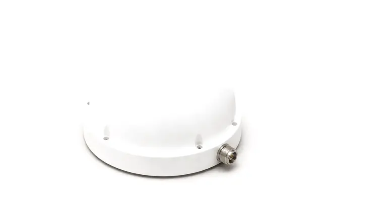
Record connector or waveguide interface, flange, fastener torque, cable bend and strain relief together with mass, envelope and center of gravity. Define wind, ice, vibration, shock, temperature, humidity, ultraviolet exposure, salt fog, sealing, drainage, corrosion control and service access. Radomes and coatings require dielectric, thickness and process control because detuning and pattern distortion may vary by batch and temperature. For arrays, preserve element spacing, amplitude and phase balance, mutual coupling, calibration path, scan volume and thermal state. A mechanically acceptable installation is not complete until the RF change caused by that installation is quantified.
Accept the installed antenna with traceable pattern evidence
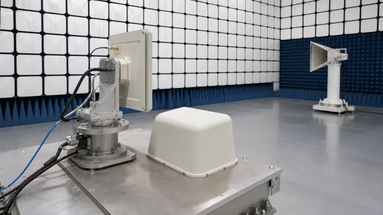
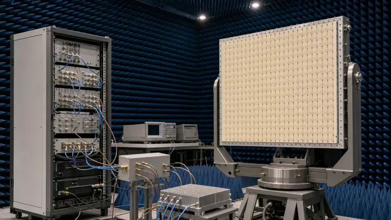
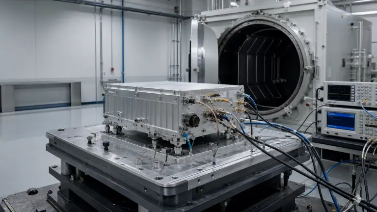
Measure S-parameters and port isolation at the declared reference plane, then characterize gain, efficiency and two- or three-dimensional patterns over frequency and polarization. Use a calibrated far-field, compact-range or near-field method with transformation where appropriate; document range geometry, quiet-zone limits, reference antenna, cable movement, alignment and uncertainty. Active antenna systems may also require EIRP, total radiated power, effective isotropic sensitivity, modulation quality and beam-state testing. Repeat critical measurements after environmental exposure and on the installed platform or a representative fixture. Acceptance records should identify hardware revision, radome, mounting state, calibration files, software or beam table, temperature and pass/fail limits.
- Use case, propagation assumptions, coverage volume, range, orientation, mobility and exclusion zones
- Bands, bandwidth, impedance, installed VSWR, realized gain, efficiency, beamwidth, sidelobes and front-to-back ratio
- Polarization, axial ratio or cross-polar discrimination, port isolation, pattern tracking and co-site coupling
- Peak and average power, duty cycle, mismatch, PIM, lightning, ESD and receiver exposure
- Aperture, ground plane, radome, mounting, connectors, cables, wind, vibration, temperature, sealing and corrosion
- Pattern method, calibration, uncertainty, beam states, environmental sequence, installed verification and revision records
Category boundary
Included are passive antenna elements, multiport antennas, arrays, feeds and integrated radiating front ends whose primary function is to transform guided RF energy into a controlled electromagnetic field or receive that field at a defined interface. Standalone amplifiers, filters, switches, cables, waveguide runs, complete radio units and complete communication systems remain in their own categories; radomes and RF windows have a dedicated material and enclosure category.
Define the installed radiation requirement before comparing antennas
- Antennas & Radiating Front Ends supplier / Antennas & Radiating Front Ends manufacturer
- Design the measurement and evidence package before purchase Conducted tests can establish port match, isolation and feed-network behavior, but radiated gain and pattern require an over-the-air method. State whether substitution gain, comparison gain, near-field transformation, compact-range or far-field measurement is acceptable....
- Antennas & Radiating Front Ends technical specifications
- Freeze continuous band coverage and the conducted reference plane List every transmit and receive range, guard band and operating state as continuous intervals. A nominal center frequency does not reveal a notch, split band or scan-state limitation....
- Antennas & Radiating Front Ends selection guide
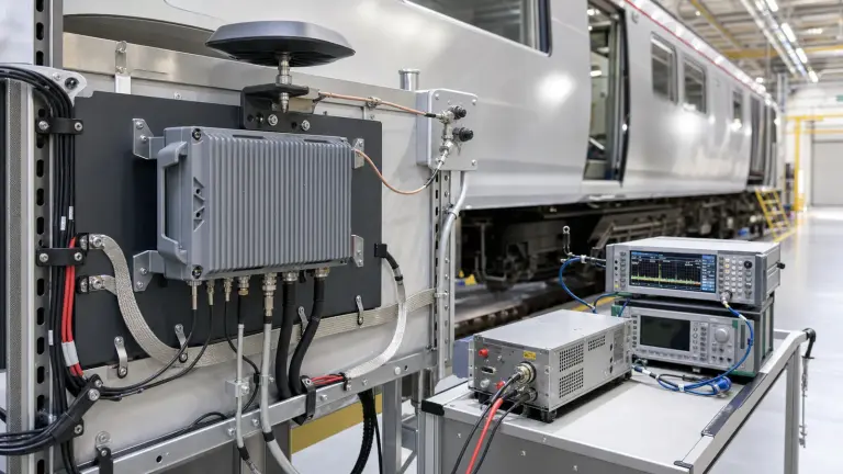
- Make the platform, radome and nearby structures part of the antenna configuration Ground plane size, mast, vehicle roof, fuselage, enclosure, cable routing, fasteners and nearby conductive equipment can alter match, pattern, efficiency, phase center and cross-polarization....
- Antennas & Radiating Front Ends test and verification
- Design the measurement and evidence package before purchase Conducted tests can establish port match, isolation and feed-network behavior, but radiated gain and pattern require an over-the-air method. State whether substitution gain, comparison gain, near-field transformation, compact-range or far-field measurement is acceptable....
How to Select an RF Antenna: Frequency, Gain, Pattern, Polarization, Match, Power and Installation
A practical antenna-selection method that turns operating band, angular coverage, gain pattern, polarization, port match, waveform power, mounting environment and measurement evidence into an RFQ and acceptance plan.