
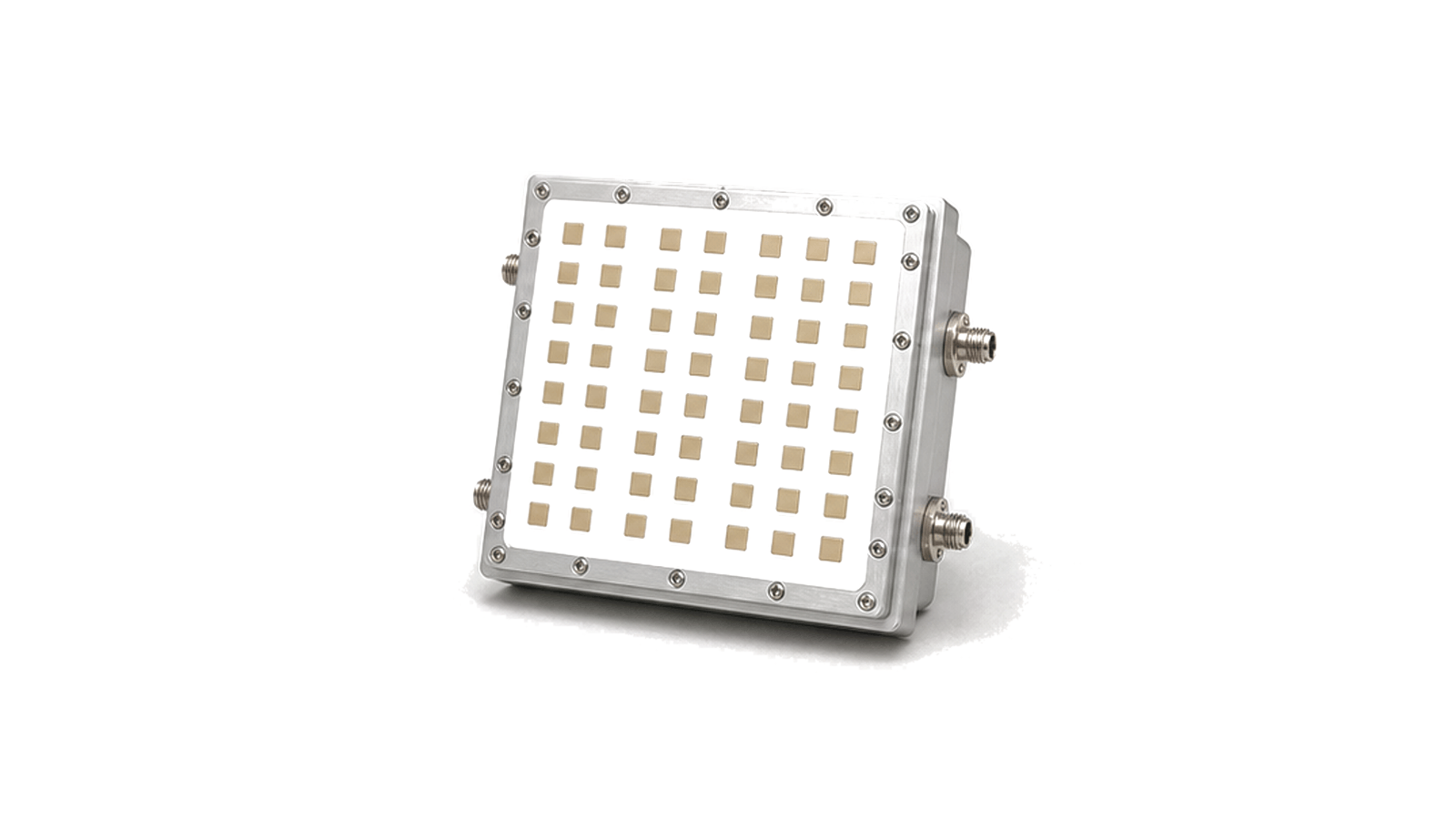
What should a phased array subassembly specification prove?
It should prove that the delivered aperture, RF channels and calibration can reproduce every required beam across the declared frequency and scan volume with bounded pointing, gain, sidelobes, polarization and thermal drift. Element count alone does not establish array performance. Element spacing, lattice, embedded element pattern, mutual coupling, amplitude taper, phase resolution, channel delay, radome and temperature determine what beams can actually be formed. The specification must define whether the item is a passive aperture, active transmit array, receive array or reciprocal subassembly, and which beamformer, control, power, clock, cooling and calibration functions are included at the delivery boundary.
Freeze the array architecture and interfaces
Define frequency range, instantaneous bandwidth, transmit-receive role, polarization, aperture size, element type, lattice, spacing in wavelengths, element and subarray count, and the subarray-to-beamformer topology. Map every RF, clock, synchronization, control, power, thermal and mechanical interface. State whether transmit-receive modules, phase and gain control, frequency conversion, couplers, calibration sources, health monitoring, radome and cooling plate are included. Document reference planes and beam-command format. Without a stable boundary, gain, noise, power and calibration claims can be shifted between the array and external equipment.
Specify performance over frequency and scan volume
Declare the usable azimuth-elevation scan volume and the beam states that must be supported. At boresight, sector edges and scan corners, specify realized gain, effective radiated power or receive sensitivity figure, beamwidth, pointing error, scan loss, sidelobe and grating-lobe limits, cross-polar response and polarization purity. Include bandwidth-dependent beam squint, element-pattern roll-off, quantized phase and amplitude states, taper loss and failed-element cases. Grating-lobe risk must be assessed from element spacing and scan angle at the highest frequency, not only from a nominal center-frequency pattern.
Control channel coherence, calibration and temperature
Set channel-to-channel amplitude, phase and group-delay tolerances across frequency, power and temperature. Define calibration reference, injected or radiated method, coupler path, measurement receiver, coefficient resolution, storage, version control and application sequence. Account for mutual coupling, connector and assembly tolerance, phase-shifter state error, local-oscillator or clock distribution, warm-up, drift and thermal gradients. Specify recalibration triggers, calibration time, allowed unavailable beams and behavior with a failed or disabled element. A correction table is valid only for the hardware revision, reference planes, frequency grid and thermal state used to create it.
Build OTA acceptance around the critical beams
Choose far-field, near-field or compact-range methods from aperture size, frequency and available quiet zone. Define probe polarization, positioner accuracy, chamber reflections, cable and path calibration, dynamic range and measurement uncertainty. Test transmit and receive paths as applicable at band edges, representative frequencies, power levels and thermal conditions. Cover boresight, maximum scan, corners, highest sidelobe risk and representative taper states; verify gain, pointing, beamwidth, sidelobes, cross-polarization, scan loss, effective radiated power or receive figure and beam-to-beam repeatability. Repeat with the production radome, cooling and control software and preserve raw data, coefficients and revisions.
- Passive or active role, band, bandwidth, polarization, aperture, element type, lattice, spacing, element and subarray count
- RF, clock, synchronization, control, power, thermal, mechanical and calibration boundaries
- Scan volume, beam table, gain, EIRP or G/T, beamwidth, pointing, scan loss, sidelobes, grating lobes and cross-polarization
- Channel amplitude, phase and group delay, control resolution, coupling, drift, warm-up, failed elements and recalibration
- Radome, cooling plate, flatness, tolerances, connectors, sealing, vibration, temperature and serviceability
- OTA range, quiet zone, probes, positioner, uncertainty, critical beams, power-temperature states, raw data and coefficient version
Category boundary and operating limits
This category covers passive or active phased-array antenna subassemblies that combine a radiating aperture with the supplied feed, channel, beam-control and calibration hardware declared at the interface. Standalone beamformer integrated circuits, phase shifters, transmit-receive modules, external converters, processors, power supplies, cooling systems, waveform generation and complete radar or communication platforms remain separate unless explicitly integrated. A subassembly specification does not establish end-system range, capacity or detection performance without the waveform, RF chain, processing, installation and environment.