
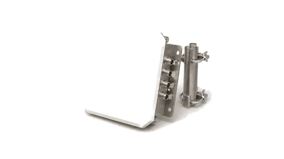
What should an anti-drone antenna specification prove?
It should prove that the installed antenna geometry can collect or resolve the intended drone-related emissions over the declared coverage while preserving sensitivity, bearing information and calibration. The antenna does not identify a drone by itself. Detection and classification depend on the receiver, signal processing, reference library and whether the aircraft or controller emits a signal the system can observe. Antenna selection determines how much of that signal reaches the receiver, from which directions and polarizations, and whether multiple channels retain the amplitude, phase or timing relationships required for direction finding or geolocation.
Separate monitoring, direction finding and lawful effector roles
State whether the antenna supports wideband passive monitoring, sector detection, angle-of-arrival direction finding, multi-site geolocation, radar support, visual cueing or an authorized RF effector. These roles require different patterns, channel counts, power limits and safety controls. Define the signals of interest by frequency range, likely bandwidth, hopping behavior, polarization and expected elevation rather than by drone brand. Passive RF detection cannot guarantee discovery of autonomous or radio-silent aircraft, and an effector antenna does not replace the legal authority, spectral coordination and interlocks required to transmit.
Design coverage from the installed RF environment
Choose 360-degree, sector or steerable coverage from the protected volume and available sensor sites. Specify azimuth and elevation pattern, realized gain, beamwidth, sidelobes, front-to-back ratio, polarization response and installed VSWR across every monitored band. For direction finding, define channel-to-channel amplitude, phase and group-delay matching, port isolation, switching or sampling timing and bearing ambiguity limits. Include cable and radome loss, receiver noise figure, strong-signal handling, nearby cellular, broadcast, radar and Wi-Fi emitters, multipath from buildings or ships and any masked sectors. A quoted range without emitter power, noise, geometry and probability criteria is not an acceptance requirement.
Preserve calibration through the mast, radome and weather
Freeze antenna orientation, height, baseline between sites, coordinate system, mast and platform structure, cable type and length, connector torque, lightning protection and grounding. Radomes, enclosures and support frames can alter pattern and phase, so characterize them as installed. Define wind, vibration, temperature, rain, ice, salt, ingress, corrosion and maintenance access. Direction-finding arrays need a field calibration method using known emitters or calibrated sources at documented azimuth and elevation. Record channel gain and phase correction, timing reference, cable replacement rules and recalibration triggers after relocation, service, impact or temperature excursion.
Validate bearing and detection performance with representative scenarios
Test known emitters across frequency, polarization, azimuth, elevation and received level in a quiet reference setup, followed by an operational-site campaign. Measure sensitivity, bearing error, probability of detection, update time, false alarms, multi-emitter behavior and recovery near strong unrelated signals. Repeat with representative hopping, telemetry and video signals, but keep the antenna result separate from classifier-library performance. At the site, survey background spectrum and multipath, verify masked directions and compare single-site bearings or multi-site fixes against surveyed positions. Acceptance must state conditions, uncertainty, software and calibration revisions, and the scenarios that remain outside the RF sensor's capability.
- Role: passive monitoring, sector warning, direction finding, multi-site geolocation, radar support or authorized effector
- Frequency bands, instantaneous bandwidth, signal types, polarization, elevation and radio-silent target limitation
- Coverage, realized gain, beamwidth, sidelobes, front-to-back ratio, installed VSWR, radome and cable loss
- DF channel count, amplitude-phase and delay matching, isolation, timing, ambiguity and expected bearing accuracy
- Site noise, strong emitters, multipath, masked sectors, mast, baseline, grounding, lightning and weather
- Reference emitters, spectrum survey, calibration, uncertainty, false alarms, detection criteria, revisions and recalibration
Category boundary and operating limits
Included are receiving, monitoring, sector and direction-finding antennas or antenna arrays primarily intended for counter-UAS RF sensing, plus antenna hardware for a legally authorized integrated effector where applicable. Monitoring receivers, signal libraries, classifiers, radars, cameras, jammers, power amplifiers and complete counter-UAS systems remain separate. The category does not imply guaranteed detection of autonomous or non-emitting aircraft and does not confer authority to transmit or disrupt radio links.