Define the installed radiation requirement before comparing antennas
The correct antenna covers the required directions, rejects the directions that matter, preserves polarization and match, accepts the real waveform and still meets its limits in the installed configuration. Start with a coordinate system and angular coverage map. Add continuous frequency coverage, port and reference-plane definitions, gain and pattern envelopes, polarization, accepted power, mechanical interfaces and environmental states. Only then compare antenna families, because maximum gain and a single VSWR value do not describe the complete radiating boundary.
Begin with spatial coverage and an installed coordinate system
Write the service volume in azimuth and elevation before naming an antenna type. A point-to-point link may need a narrow main beam and controlled sidelobes; a mobile platform may need coverage through a large elevation range; a navigation receiver may need an upper-hemisphere pattern while rejecting low-elevation interference; an array may need a scan volume rather than one boresight direction. Mark regions that must be served, regions where gain may fall, and regions that require a null, sidelobe ceiling or front-to-back limit.
Define zero angle, positive rotation, antenna boresight, platform axes, polarization basis and installed orientation. State whether the pattern is required in principal cuts or over a three-dimensional grid and whether values are realized gain, gain, directivity or normalized pattern. Without those definitions, two technically correct plots can describe different quantities and cannot be used for acceptance. Mechanical datums and the RF coordinate system should be traceable to the same drawing.
Freeze continuous band coverage and the conducted reference plane
List every transmit and receive range, guard band and operating state as continuous intervals. A nominal center frequency does not reveal a notch, split band or scan-state limitation. If one antenna serves several services or ports, identify simultaneous operation, diplexing, bias networks, integrated filters and any band-specific cable or transition. The declared antenna band is the range over which all required limits remain valid, not merely the range where some energy is radiated.
Name the plane where impedance, return loss, VSWR and accepted power apply: connector face, waveguide flange, cable end, board launch or antenna element feed. State which adapter, feed line, balun, matching network, bias tee and transition losses are included. Return loss and VSWR describe reflection at that plane; they do not prove radiation efficiency, pattern or polarization. Preserve complex S-parameters when phase or multiport coupling matters.
Specify a gain-pattern envelope rather than one maximum-gain number
Maximum gain is one point on one pattern at one frequency and polarization. A usable specification may also need minimum gain inside the service region, ripple, half-power beamwidth, first-null beamwidth, sidelobe envelope, null depth, front-to-back ratio and cross-polar level. Apply each limit over frequency and, for arrays, over scan angle. A broad coverage requirement can conflict with high peak gain, so the system must decide which angular regions carry the link or sensing budget.
Directivity describes how concentrated the radiation is relative to an isotropic source; gain also includes dissipative efficiency. Realized gain additionally includes mismatch at the declared port. These quantities are related but not interchangeable. If a proposal reports only directivity, the accepted power and radiated result remain unknown until conductor, dielectric, matching and feed losses are accounted for. Ask for the quantity, polarization, frequency, coordinate convention and measurement method with every pattern file.
Treat polarization, ports and array behavior as first-class requirements
For linear polarization, define orientation and allowable cross-polar response over the service angles. For circular polarization, define right- or left-hand sense using the agreed viewing convention and set axial-ratio limits over frequency and angle. A circularly polarized label at boresight does not guarantee useful polarization at the edge of coverage. Polarization mismatch belongs in the system budget and should not be hidden inside a generic margin.
Dual-polarized, diversity, MIMO and array antennas add port isolation, envelope correlation, embedded-element pattern, amplitude and phase balance, scan loss and coupling. Specify whether patterns are measured with unused ports terminated and whether active elements are driven individually or as a beam state. For a calibrated array or navigation antenna, phase center and group-delay behavior may matter as much as peak gain.
Translate the real waveform and environment into accepted port stress
State CW, average and peak power, pulse width, duty cycle, modulation crest factor, number of simultaneous carriers, source and load mismatch, reverse power and temperature at each port. A single power rating cannot represent heating, electric-field peaks and breakdown risk under every waveform. High-power limits can depend on frequency, geometry, spacing, pressure, contamination, connector condition and mismatch; pulse and altitude conditions therefore belong in the RFQ and test plan.
Separate electrical survival from performance retention. An antenna may survive a high-power pulse yet detune, heat, generate passive intermodulation or change polarization. Environmental requirements can include temperature, altitude, pressure, humidity, salt, icing, wind, vibration, shock, ingress, vacuum or solar loading. Define which RF parameters are checked during exposure and which are remeasured afterward.
Make the platform, radome and nearby structures part of the antenna configuration
Ground plane size, mast, vehicle roof, fuselage, enclosure, cable routing, fasteners and nearby conductive equipment can alter match, pattern, efficiency, phase center and cross-polarization. A radome can add loss, reflection, beam shift and polarization error, especially as frequency, incidence angle, moisture or temperature changes. If the delivered system uses a radome, acceptance evidence should represent that radome, its spacing, material state and attachment.
Freeze mounting datums, keep-out zones, cable exit, connector torque, grounding, bonding, drainage and allowable installation tolerances. Decide whether supplier acceptance is for the stand-alone antenna, an agreed representative ground plane, a supplied radome assembly or the final platform. When the final platform cannot be placed in the range, define a correlation plan using simulation, representative fixtures, near-field scanning or installed check measurements.
Design the measurement and evidence package before purchase
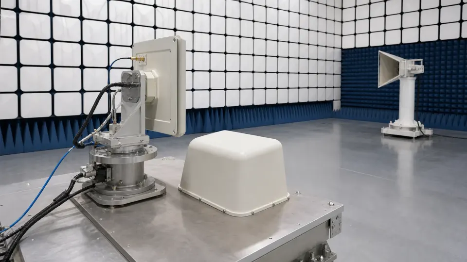
Conducted tests can establish port match, isolation and feed-network behavior, but radiated gain and pattern require an over-the-air method. State whether substitution gain, comparison gain, near-field transformation, compact-range or far-field measurement is acceptable. Control range reflections, quiet-zone quality, alignment, cable movement, positioner accuracy, receiver linearity, dynamic range, reference-antenna calibration and mismatch. The uncertainty statement must match the frequency, polarization and angular metric being accepted.
Request native pattern data rather than screenshots alone. Preserve frequency, polarization, port state, beam state, angle convention, angular step, units, normalization, calibration identity, uncertainty, fixture, radome and environmental condition. Tie files to serial number and revision. A plotted curve without this metadata is difficult to compare, reproduce or use in a system model after the hardware changes.
| Decision boundary | Requirement to freeze | Reject the proposal when |
|---|---|---|
| Coverage and coordinates | Installed axes, service and exclusion angles, pattern cuts or 3D grid | Only an unreferenced beamwidth is supplied |
| Band and ports | Continuous ranges, port states, impedance and named conducted plane | Only a center frequency or connector name is shown |
| Gain and pattern | Realized-gain envelope, ripple, sidelobes, nulls and front-to-back limits | One typical maximum-gain value represents the antenna |
| Polarization | Orientation or sense, axial ratio, cross-pol, port isolation and angle range | The proposal says only linear or circular |
| Power and environment | CW, average, peak, pulse, duty, mismatch, pressure, temperature and exposure | A power number has no waveform or environmental boundary |
| Installed configuration | Ground plane, platform, radome, spacing, cable route, datum and tolerance | Free-space data is presented as installed performance |
| Acceptance evidence | Method, calibration, uncertainty, raw data, metadata and revision traceability | Only a plot image or simulated peak is offered |
Worked check: a 2:1 VSWR is not a complete antenna efficiency result
For a 2.0:1 VSWR at the declared port, the reflection-coefficient magnitude is (2-1)/(2+1) = 0.333. Reflected power is therefore about 11.1%, equivalent to a return loss of about 9.54 dB and a mismatch loss of about 0.51 dB. That arithmetic describes mismatch only. If conductor, dielectric, feed and radome losses total another 1.2 dB, realized gain can be roughly 1.7 dB below directivity before installation effects. A favorable VSWR can still coexist with low radiation efficiency or a distorted pattern, so match, gain and pattern require separate evidence.

Verify from the conducted port to the installed radiation boundary
- Approve continuous frequency ranges, port states, waveform power, coordinate system, service volume and exclusion regions.
- Freeze the antenna, feed, cable, adapters, mounting datum, ground plane, radome and platform configuration by revision.
- Calibrate conducted fixtures to the named plane and measure complex return loss, isolation and coupling over frequency and environment.
- Measure co-polar and cross-polar patterns with declared angular steps, frequency points, port terminations and beam states.
- Determine gain or realized gain with a traceable reference antenna and an uncertainty budget appropriate to the band.
- Verify sidelobes, nulls, front-to-back ratio, beamwidth, axial ratio and scan loss over the required angular region rather than boresight alone.
- Apply approved CW or pulsed stress with real duty, crest factor, mismatch, pressure and temperature; inspect detuning, heating and damage.
- Repeat critical measurements with the radome and representative platform, then correlate any final installed check to the range result.
- Trend unit-to-unit and remount repeatability where production, calibration or interchangeability depends on the antenna.
- Retain raw S-parameters, pattern grids, calibration identities, uncertainty, coordinates, photos without people, serials, revisions and deviations.
Antenna-selection failures that survive a catalog comparison
- Selecting maximum gain before defining the angular coverage volume
- Using directivity, gain and realized gain as if they were the same quantity
- Accepting a single center-frequency plot for a continuous-band requirement
- Treating good VSWR as proof of radiation efficiency or pattern quality
- Specifying circular polarization without sense, axial ratio and angle range
- Ignoring cross-polarization, sidelobes or null depth outside boresight
- Applying one nominal power rating to a different pulse, mismatch, pressure or temperature
- Testing the antenna without the radome, ground plane or nearby structure used in service
- Comparing simulated and measured plots with different normalization or coordinate conventions
- Keeping screenshots while discarding native pattern data, calibration and revision metadata
Information required for an RF or microwave antenna RFQ
- Use case, installation, platform axes, service volume, exclusion regions and pointing or scan behavior
- Continuous transmit and receive ranges, guard bands, port count, simultaneous states and impedance
- Realized gain or gain limits by angle and frequency, beamwidth, ripple, sidelobes, nulls and front-to-back ratio
- Linear orientation or circular sense, axial ratio, cross-polar discrimination and port isolation
- Conducted reference plane, connector or waveguide, cable, balun, matching network and included losses
- CW, average, peak and pulse power, duty, crest factor, carriers, mismatch, reverse power and temperature
- Ground plane, radome, enclosure, keep-out zone, mounting datum, envelope, mass, cable exit and grounding
- Temperature, altitude, pressure, humidity, salt, ice, wind, vibration, shock, ingress, vacuum or contamination
- Single-port, diversity, MIMO or array states, beam steering, phase center, coupling and calibration needs
- Conducted and radiated test methods, frequency points, angle grid, polarization basis and acceptance limits
- Calibration traceability, measurement uncertainty, native data format, serial linkage and change control
- Required samples, first-article evidence, production sampling, remount repeatability and installed correlation
Continue the antenna engineering decision
- Browse RF antennas and radiating front-end families
- Review antenna requirements for microwave backhaul links
- Review antenna and aperture needs in radar and RF sensing
- Review navigation receiver front-end constraints
- Review antenna feed and matching integration
- Send the coverage, platform, waveform and acceptance requirements