

LCRF

Privacy preferences

Choose optional purposes independently. You can change or withdraw your choice at any time from the footer.

Strictly necessary

Required for security, session functions and storing your privacy choice.

Always active
Preferences

Remembers optional display or language settings when these features are enabled.

Analytics

Uses first-party visitor and session identifiers to measure pages, referrals and inquiry interactions.

Marketing

Allows marketing measurement or third-party advertising technologies if they are introduced in the future.

Mobile, Airborne and Naval Antennas

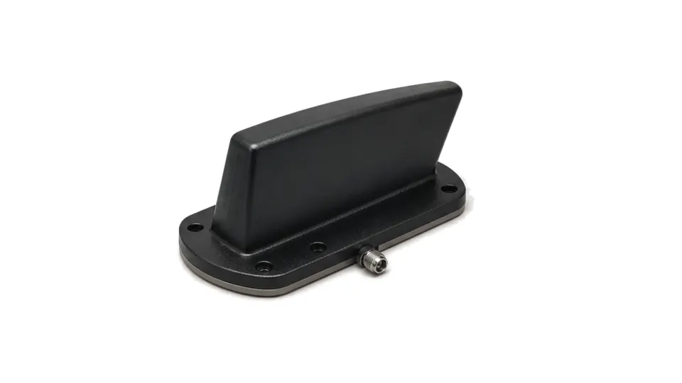
Mobile, airborne and naval antennas are selected as installed platform interfaces, with coverage, ground-plane, co-site, environmental and mechanical constraints.

Mobile, Airborne & Naval Antennas

Articles

FAQ

How are environmental and EMC tests tailored for rail, maritime, road and airborne RF hardware?

Derive test category, severity, axes, harness, operating modes and pass criteria from the exact installation rather than treating a platform standard as a universal certificate.

What must be specified for a mobile-platform RF antenna and coax installation?

Define the installed antenna boundary, body or ground plane, feedthrough, protection, complete coax route, reference planes, mechanical support and replacement limits.

What serviceability and lifecycle evidence should accompany mobile RF hardware?

Deliver installation identity, maintainability limits, acceptance results, diagnostics, spares and configuration-controlled change triggers that keep field evidence valid.

How should vehicle power transients, returns and chassis bonding be specified for RF hardware?

Specify the voltage and transient at the equipment terminals with source impedance and harness state, then control returns, shields and chassis bonds as separate verified paths.

Engineering inquiry

Share your RF requirement

Share the product, operating requirements and project context. Our engineering team will route your request to the right specialist.

AttachmentsAttach drawings, BOMs, specifications or test files. Up to 5 files, 10 MB each and 25 MB total.
or drag and dropPDF, DOCX, XLSX, CSV, TXT, JPG, PNG, S1P and S2P
Typically reviewed within one business dayProject information is handled confidentially

What determines the suitability of a platform-mounted RF antenna?

Suitability is determined by installed coverage, matching, efficiency and isolation on the real platform, together with mechanical and environmental survival—not by free-space antenna data alone. This family covers antennas integrated on vehicles, aircraft and vessels. Fixed base-station, SATCOM terminal, GNSS-only and purpose-built anti-drone families retain their own query ownership.

Define the link and coverage on the platform

Specify operating bands, simultaneous services, polarization, required azimuth and elevation coverage, gain or efficiency, accepted nulls, transmit power, receiver sensitivity and feed-line loss. Antenna location, platform shadowing, nearby structures, radomes and the conductive ground plane can change match, pattern and polarization.

Treat mounting and environment as RF design inputs

Record mounting footprint, skin or deck material, bonding, grounding, drainage, sealing, connector orientation, cable route and service access. Airborne installations add aerodynamic load, altitude, pressure and icing concerns; naval installations add salt, spray and corrosion; mobile installations add vibration, impact, vehicle noise and changing surroundings.

Verify installed performance and co-site behavior

Measure installed VSWR or return loss, cable loss, radiation pattern or coverage, polarization and isolation from nearby transmitters and receivers. Exercise all relevant radios and platform states to expose desensitization, intermodulation, switching and conducted or radiated interference. Mechanical inspection and environmental evidence complete the acceptance record.

  • bands, services, polarization and coverage envelope
  • installed gain, efficiency, match and accepted pattern nulls
  • ground plane, bonding, mounting, radome and cable route
  • transmit power, feed loss and receiver sensitivity
  • co-site spacing, isolation, filtering and intermodulation cases
  • temperature, vibration, moisture, corrosion, altitude and maintenance access

Acceptance boundary

Approve the antenna with its mount, ground plane, radome, feed line and neighboring RF systems represented. Bench VSWR or a free-space pattern does not prove installed coverage, co-site compatibility or environmental integrity.