
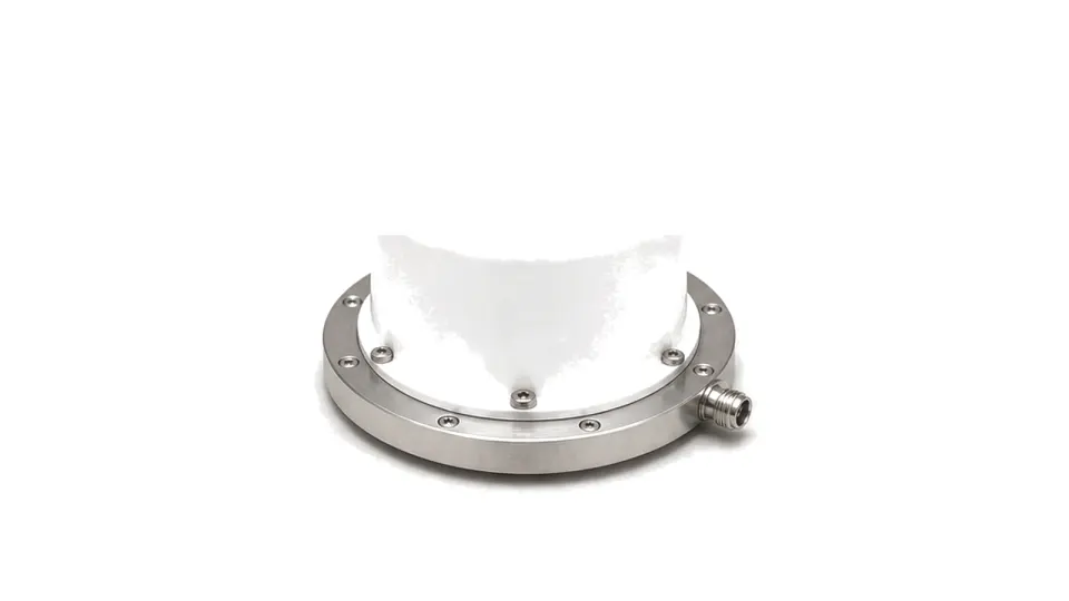
What is the engineering purpose of a radome or RF window?
A radome or RF window is a dielectric barrier that protects an antenna, feed or microwave aperture while allowing the required electromagnetic field to pass with controlled loss and distortion. A radome usually encloses an antenna; an RF window often closes a local aperture or pressure boundary. Neither is electrically invisible, so the useful specification belongs to the installed antenna-window system rather than to material strength or nominal transparency alone.
Match material and wall construction to the field
Relative permittivity, loss tangent, moisture absorption, wall thickness, core and coating determine electrical thickness and heating. Frequency, angle of incidence, polarization and scan range must be evaluated together. A wall optimized near normal incidence can reflect or shift phase at oblique scan angles, while manufacturing thickness variation moves the designed transmission condition.
Protect the radiation pattern, not only insertion loss
Review one-way transmission loss, reflection, phase delay, boresight error, gain change, sidelobes, beamwidth, axial ratio and cross-polarization with and without the structure. Seams, fasteners, lightning features, conductive finishes and local curvature can create asymmetry. Phased arrays and tracking antennas require data across steering angle and polarization state.
Qualify the environmental state that the RF system will see
Rain films, absorbed moisture, ice, salt, dust, ultraviolet exposure, temperature, pressure, impact and erosion can change dielectric behavior or wall geometry. Define sealing, venting, drainage, coating repair and inspection. Material coupons support screening, but final acceptance normally compares the antenna pattern and transmission before and after installation and environmental conditioning.
- frequency band, polarization, antenna scan range and incidence angles
- permittivity, loss tangent, thickness tolerance, core and coating
- transmission loss, reflection, phase delay and power heating
- boresight shift, gain, beamwidth, sidelobes, axial ratio and cross-pol
- rain, wetting, ice, temperature, UV, salt, pressure, impact and erosion
- seams, fasteners, sealing, venting, drainage and installed test method
Acceptance boundary
Approve the radome or RF window from installed antenna measurements over the required frequency, scan, polarization and environmental states. A flat coupon loss value alone cannot establish boresight, sidelobe or wet-weather performance of the finished structure.