
LCRF

Privacy preferences

Choose optional purposes independently. You can change or withdraw your choice at any time from the footer.

Strictly necessary

Required for security, session functions and storing your privacy choice.

Always active
Preferences

Remembers optional display or language settings when these features are enabled.

Analytics

Uses first-party visitor and session identifiers to measure pages, referrals and inquiry interactions.

Marketing

Allows marketing measurement or third-party advertising technologies if they are introduced in the future.

Beamforming Module Integration

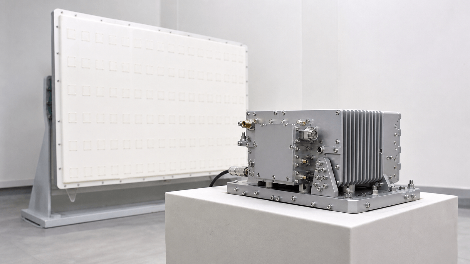
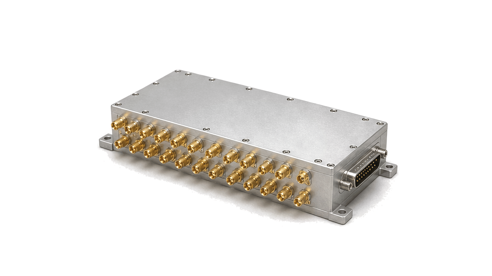
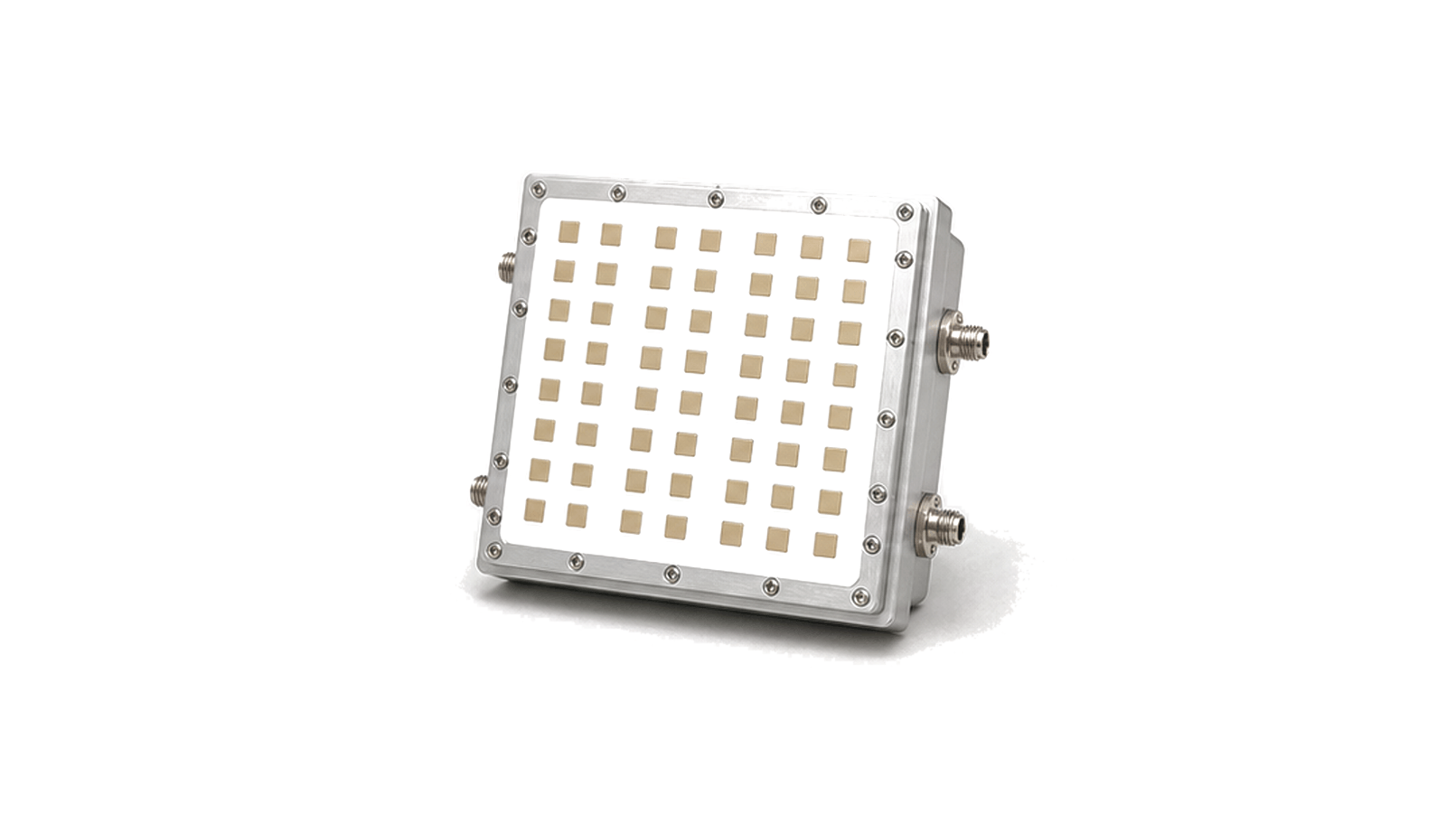
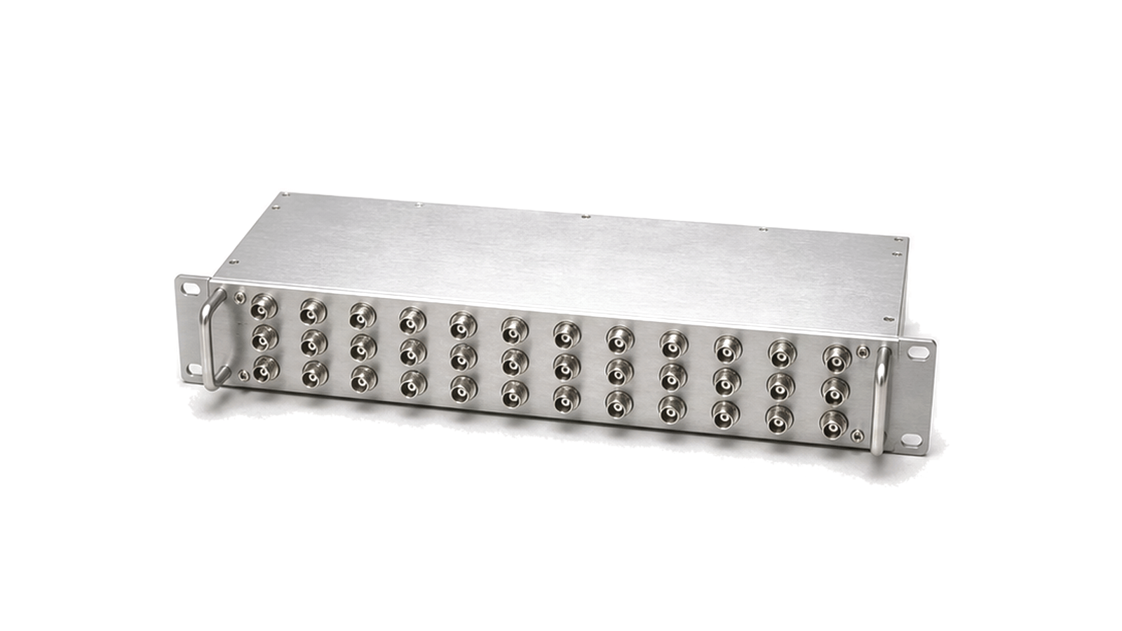
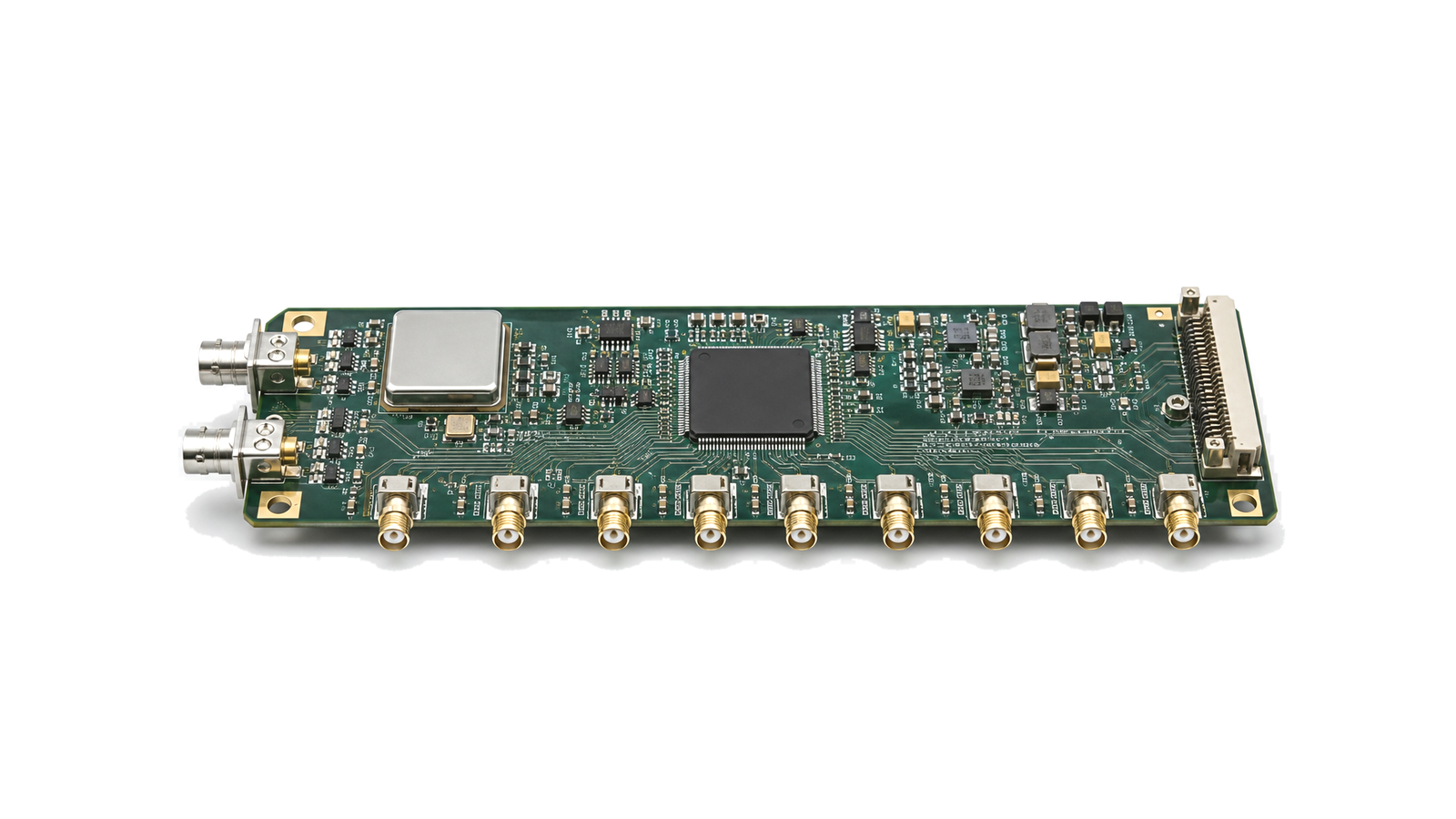
Beamforming module integration brings phase control, amplitude balance, timing reference, RF distribution and antenna-port hardware into a matched multi-channel front end.

Beamforming Module Integration RF solution visual

Beamforming Module Integration

Beamforming module integration aligns multiple RF paths so antenna elements, distribution networks, gain stages, timing references and control interfaces operate as one coordinated front end. It is used in phased-array radar, space payload support and other systems where channel-to-channel consistency determines radiation pattern behavior.

System boundary

The work centers on phase control, amplitude balance, reference distribution, RF path loss, isolation, connector routing, power delivery and thermal placement. Mechanical layout matters because cable length, antenna spacing and module mounting can change the final array response.

Engineering data

Useful records include channel count, frequency band, phase range, amplitude trim range, distribution loss, timing reference, antenna interface, control method, operating temperature and enclosure limits.
Articles

FAQ

How do amplitude and phase errors affect a phased-array radar RF front end?

Channel amplitude and phase errors change coherent addition, beam direction, gain, sidelobes and null depth; their allowed distribution must be tied to the array pattern and calibration model.

Why can an installed antenna pattern differ from the free-space data sheet?

Ground planes, structures, cables, radomes and mounting tolerances change current distribution and scattering, which can alter match, gain, pattern, polarization and phase center.

What is the difference between antenna gain, directivity, beamwidth and sidelobes?

Directivity describes angular concentration, gain includes dissipative efficiency, beamwidth describes main-beam extent and sidelobes describe radiation outside that beam.

Engineering inquiry

Share your RF requirement

Share the product, operating requirements and project context. Our engineering team will route your request to the right specialist.

AttachmentsAttach drawings, BOMs, specifications or test files. Up to 5 files, 10 MB each and 25 MB total.
or drag and dropPDF, DOCX, XLSX, CSV, TXT, JPG, PNG, S1P and S2P
Typically reviewed within one business dayProject information is handled confidentially