
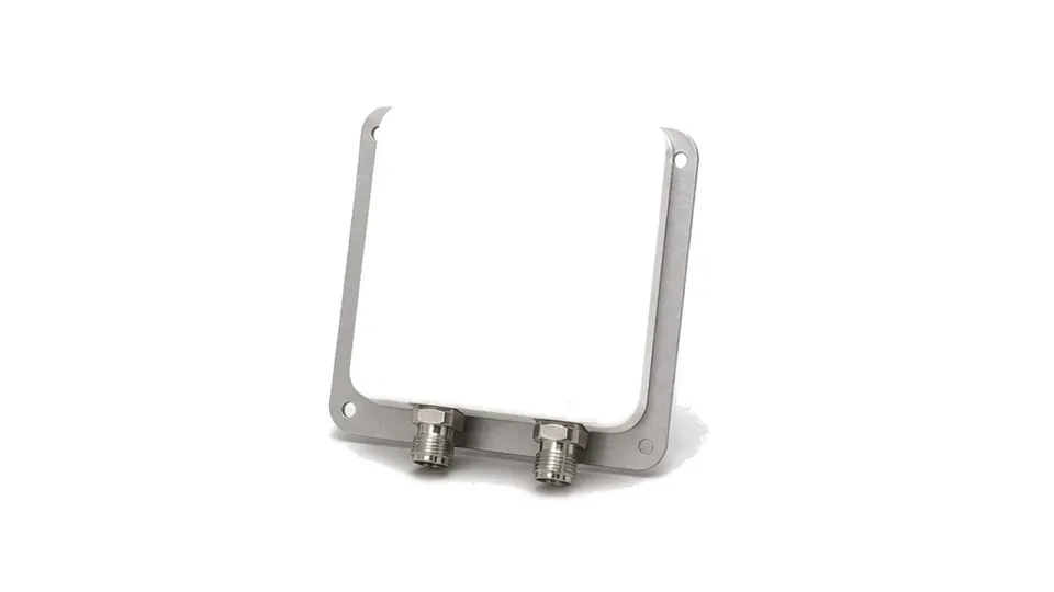
What should a dual-polarized antenna specification prove?
It should prove that two defined polarization ports produce distinct and repeatable radiation responses with sufficient discrimination and isolation across the required band, angles and installed environment. Two connectors do not by themselves prove useful dual-polarization performance. The result depends on the polarization basis, feed or orthomode structure, shared aperture, radome, port balance and the angle over which the system must separate or combine channels. Dual polarization can support diversity, spatial transmission or polarimetric sensing, but capacity, detection quality and channel independence also depend on the radio paths and propagation environment.
Define the polarization basis and viewing convention
State whether the ports are vertical-horizontal, plus/minus 45-degree linear, right-left circular or another orthogonal basis. Define the coordinate system, boresight, reference plane, viewing direction and connector labels; circular-polarization handedness reverses when the viewing convention changes. Identify transmit, receive or reciprocal operation and whether the purpose is polarization diversity, spatial multiplexing, interference rejection or polarimetric measurement. If a shared feed, polarizer or orthomode junction is integrated, freeze that interface because it contributes directly to isolation, phase and cross-polar response.
Specify co-polar and cross-polar behavior over angle
Request realized gain and both co-polar and cross-polar azimuth and elevation patterns for each port at representative frequencies. Set angular masks for beamwidth, boresight, sidelobes, front-to-back ratio and cross-polar discrimination, not only a single boresight value. Compare pattern tracking between the two ports, port-to-port isolation, return loss or VSWR, differential phase, group delay and phase-center stability where system processing uses channel phase. For diversity or spatial channels, define the accepted pattern correlation under the intended propagation model; for sensing, preserve the polarization purity and calibration matrix needed by the estimator.
Control feed, cable, radome and mounting asymmetry
Port balance can be degraded by connector transitions, feed tolerances, cable length, bends, torque, moisture, radome thickness, brackets and nearby metal. Specify amplitude and phase balance through the delivered reference planes and identify whether cables are included in the calibration. Preserve port labels and polarization orientation from drawing to installation; a swapped pair or a rotated antenna can look electrically healthy while invalidating polarization processing. Include power handling, passive intermodulation where high carriers share the aperture, environmental sealing, temperature, vibration and recalibration after feed, cable or radome replacement.
Measure the full two-port response and radiated matrix
Use a calibrated network analyzer to measure reflection and transmission terms for all port combinations across frequency and temperature. In an antenna range, align the coordinate system and measure gain, beam pointing, co- and cross-polar patterns, discrimination, isolation and phase for both ports with the production radome and mount. Record probe polarization, range uncertainty, cable de-embedding and reference planes. Repeat critical angles and band edges, then verify on-site port mapping, orientation, cable equality and isolation. Acceptance should distinguish antenna polarization error from receiver imbalance, propagation depolarization and digital calibration.
- Polarization basis, coordinate system, viewing direction, boresight, port labels and handedness
- Frequency range, gain, beamwidth, pointing, sidelobes, front-to-back ratio and pattern tracking for both ports
- Co- and cross-polar patterns, angular discrimination mask, port isolation, return loss or VSWR and differential phase
- Feed or orthomode boundary, connector transitions, cable reference planes, amplitude-phase balance and phase center
- Power, passive intermodulation, radome, mount, moisture, temperature, vibration, replacement and recalibration
- Full scattering-parameter matrix, chamber method, probe polarization, uncertainty, production configuration and site checks
Category boundary and operating limits
This category covers antenna assemblies that provide two declared orthogonal polarization channels, including an integrated feed, polarizer or orthomode function when supplied as part of the antenna. Standalone feed networks, hybrids, beamformers, receivers, transmitters, calibration processors and complete communication or radar systems remain separate. Dual-polarized hardware does not by itself guarantee uncorrelated channels, throughput gain or polarimetric accuracy without the propagation, RF-chain and calibration conditions.