
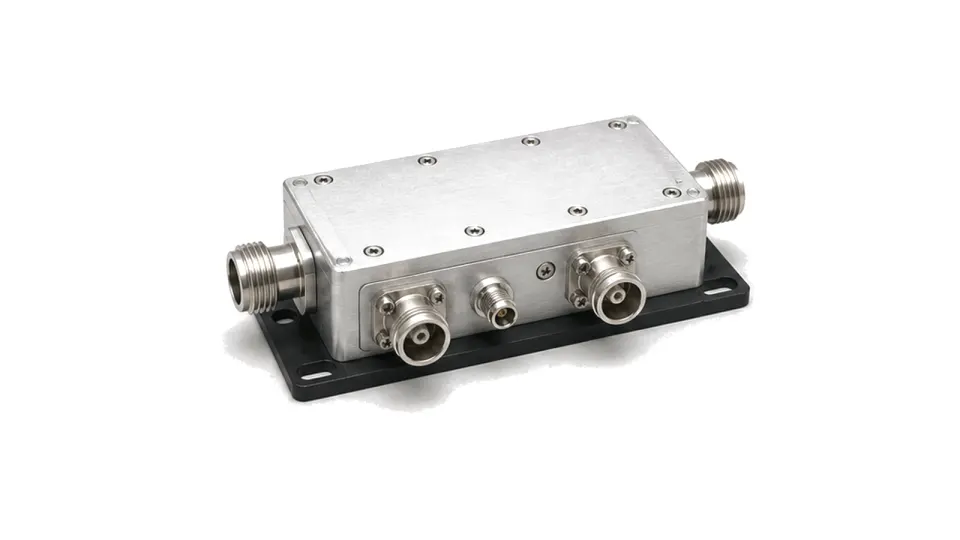
What does a VSWR and reflected power monitor measure?
A VSWR and reflected power monitor samples the waves travelling toward and returning from a load, then reports forward power, reflected power, return loss or VSWR for supervision and protection. The monitor may combine a directional coupler, detectors, conversion electronics and alarm logic. It is not interchangeable with a bare coupler or a single RF detector because usable performance depends on the complete forward and reverse measurement path.
Start with directionality and the power measurement range
Frequency range, coupling factor, directivity, insertion loss and main-line power handling establish whether the sampled signals are trustworthy. Detector dynamic range, linearity, temperature drift and calibration determine the useful forward and reflected power range. Directivity becomes especially important when measuring a small reflection beside a large forward wave.
Define the response required by the transmitter
CW, pulsed and changing-envelope systems need different detector bandwidth, averaging, peak capture and response time. Protection logic should state threshold units, hysteresis, debounce, latching, reset behavior and the safe action when a sensor or control link fails. A fast alarm is only useful when its uncertainty and transient response are known.
Calibrate at the system reference plane
Cable loss, coupler orientation, connector mismatch and the distance to the load change the relationship between sampled power and the antenna or DUT plane. Define detector calibration, forward and reverse correction, zero behavior, output scaling and uncertainty across frequency, temperature and power. Near a well-matched load, uncertainty should be stated as reflected power or return loss rather than an unstable high VSWR number.
- frequency band, impedance, main-line power and allowable insertion loss
- coupling factor, directivity and forward-to-reverse isolation
- detector range, linearity, accuracy, drift and minimum measurable reflection
- CW or pulse behavior, response time, averaging and peak capture
- alarm thresholds, hysteresis, latch, reset, fail-safe and control interface
- calibration plane, correction data, uncertainty and environmental test limits
Acceptance boundary
Approve the monitor from corrected forward and reflected power measurements at the declared reference plane over frequency, temperature, power and waveform conditions. A displayed VSWR value without directivity, uncertainty and response evidence is not a protection qualification.