
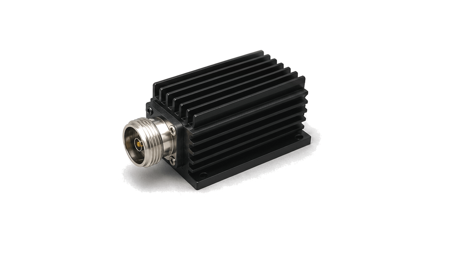
What is an RF load or dummy load?
An RF load is a non-radiating termination that presents the specified impedance and converts incident RF power into heat. It can replace an antenna during transmitter setup, absorb an isolator or circulator reject signal, terminate a hybrid port or provide a known load on an unused measurement port. A precision low-power termination and a high-power dummy load serve different purposes: the first prioritizes characterized reflection and traceability, while the second prioritizes safe energy absorption and thermal control. Neither should be selected from wattage alone.
Establish the electrical and mechanical reference first
Match characteristic impedance, connector or waveguide band, flange, sex, mounting and calibration plane to the system. Specify the full operating band and maximum reflection as return loss, reflection coefficient or VSWR across that band and temperature range. Include adapter and cable effects when the reference plane is not at the load input. For a VNA or calibration application, require traceable S-parameter data and connector condition limits; a transmitter service load with an acceptable system VSWR is not automatically a calibration standard.
Convert waveform power into a thermal requirement
State continuous or average power, peak envelope power, pulse width, repetition rate, duty cycle and expected mismatch. Average and peak limits interact through resistor voltage stress, connector field strength and temperature rise. Apply the manufacturer's derating for ambient temperature, altitude, mounting orientation and cooling method. Convection, conduction, oil and water cooling each need installation conditions; water-cooled loads require minimum flow, inlet temperature, pressure and interlocks. Include power routed from a circulator during worst-case antenna mismatch, not only normal forward power.
Verify match and heat handling under the intended installation
Inspect the connector, flange, absorber, coolant and mounting before test. Measure S11 or VSWR with a calibrated network analyzer at the defined plane and repeat after thermal stabilization where the rating demands it. Run a controlled power soak using the specified waveform and cooling, monitor case or coolant temperature, flow and reflected power, and confirm alarms or shutdowns. Record warm-up, cooldown, duty-cycle limits and the condition after overload. Acceptance should prove both safe dissipation and the required match; a cool enclosure does not prove that the resistor or connector stayed within limit.
- Characteristic impedance, connector or flange, waveguide band, sex and reference plane
- Frequency band and maximum VSWR or return loss over temperature
- Average power, peak power, pulse width, repetition rate, duty cycle and mismatch
- Cooling method, ambient, altitude, orientation, airflow or coolant flow and interlocks
- Mounting, clearances, connector voltage/current limits, service and cooldown
- Calibrated reflection test, power soak, thermal evidence, traceability and inspection criteria
Category boundary
Included are coaxial and waveguide terminations whose primary function is to absorb RF energy at a defined impedance, from precision loads to high-power dummy loads. Through-line attenuators, power sensors, antennas, RF absorbers for free-space treatment, calibration kits as complete sets and generic power resistors belong elsewhere.