High Power Amplifier Supply & Cooling
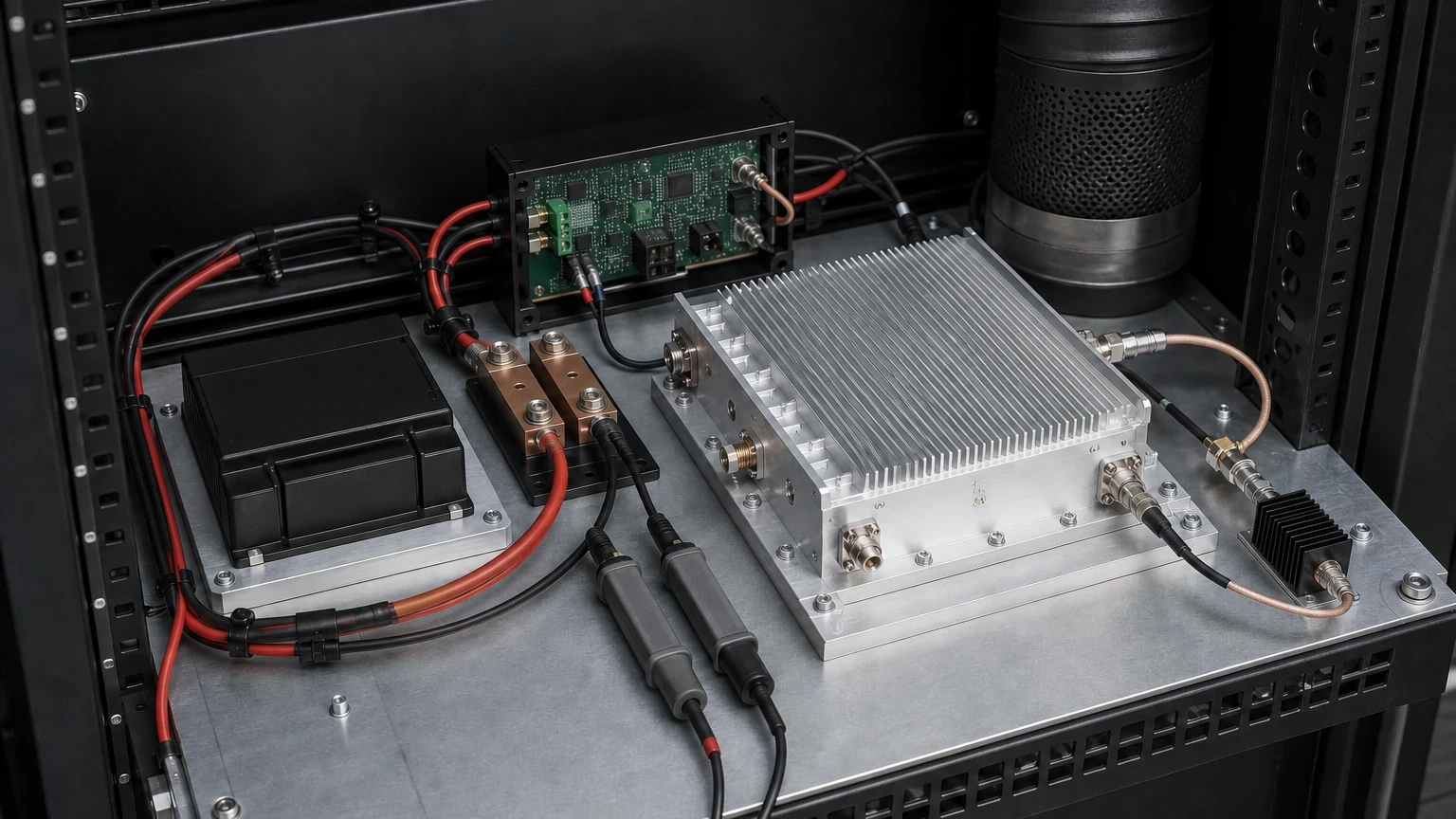
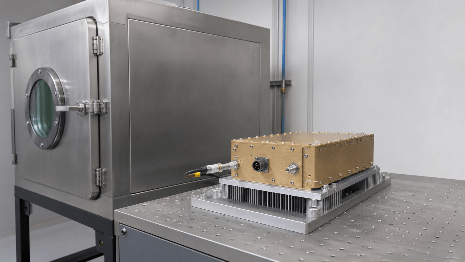
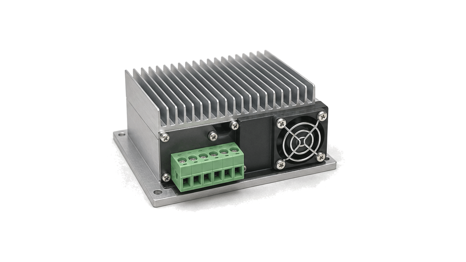
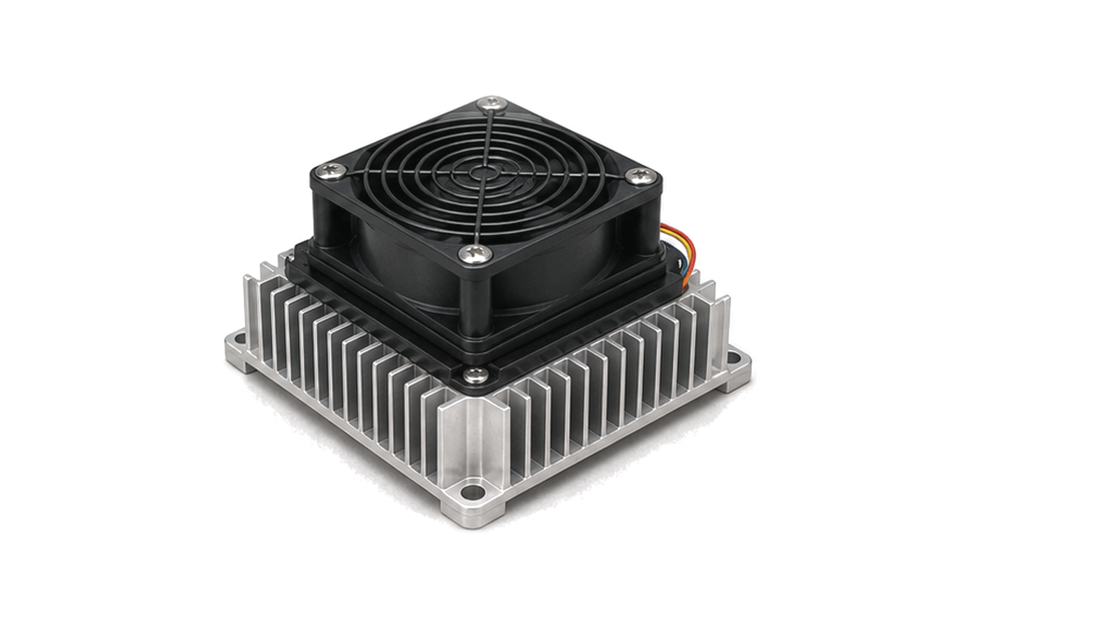
High-power amplifier supply and cooling connects the RF power stage to the electrical and thermal infrastructure that keeps it usable under load. The chain starts at the PA supply rail and bias/control input, passes through current monitoring and protection logic, and ends at the heat sink, cold plate, fan path or liquid loop that removes dissipated power.
Power and thermal path
Typical projects define supply voltage, available current, duty cycle, efficiency, heat load, inlet temperature and airflow or coolant flow together. Reflected-power or VSWR monitoring is usually part of the same boundary because mismatch events can change device dissipation faster than the mechanical cooling system can respond.
Monitoring and protection
Useful data includes voltage limits, current margin, temperature sensor locations, fault outputs, shutdown thresholds and recovery behavior. These values keep the supply, cooling assembly and amplifier protection logic aligned before the PA is placed into a transmitter, test rack or industrial RF system.
Define one electrical-and-thermal operating envelope
- High Power Amplifier Supply & Cooling architecture
- Keep the article boundary on support hardware This workflow owns the DC source and conversion path, bias generation and sequencing, enable logic, protection and telemetry, module heat flow, cooling interface and the acceptance evidence that joins them....
- High Power Amplifier Supply & Cooling design requirements
- Keep the article boundary on support hardware This workflow owns the DC source and conversion path, bias generation and sequencing, enable logic, protection and telemetry, module heat flow, cooling interface and the acceptance evidence that joins them....
- High Power Amplifier Supply & Cooling integration
- Close the path from module baseplate to ambient or coolant Define the heat-spreader or cold-plate material, contact area, flatness, surface finish, interface material, thickness, compression, fastener pattern and torque. Allocate thermal resistance across module, interface, spreader, sink and fluid or air path....
- High Power Amplifier Supply & Cooling test and verification
- Design one acceptance matrix that joins electrical, RF and thermal evidence Measure source and module-terminal voltage, rail current, enable and bias timing, fault response and declared temperatures while the RF module operates in the approved states....
How to Specify Power, Bias, Protection and Thermal Interfaces for an RF Power Module
An engineering workflow for turning RF operating modes into DC rail, current transient, ripple, sequencing, protection, heat-load, cooling-interface and acceptance requirements without confusing catalog ratings with delivered system performance.