How should RF power, thermal and reliability be designed and verified?
Start with the operating mission profile and power-state matrix. Bound electrical input, dissipated power and junction or channel temperature through the complete thermal path; define bias sequence, monitoring, derating and protection for normal and fault loads; then verify steady-state and transient temperature, RF performance, load mismatch, thermal cycling and recovery with the delivered mechanical and cooling interfaces. An RF module can meet room-temperature gain and output-power targets yet fail after installation because its supply transient, baseplate, airflow, duty cycle or reflected load differs from the characterization setup. Power delivery, heat flow and reliability are therefore one engineering problem. The design baseline must state what the module transmits, for how long, at which ambient and mounting condition, how quickly it can cool, and what the controller does before an electrical or thermal limit becomes damage.
Engineering decisions covered
- RF Power, Thermal and Reliability architecture: translates waveform, duty cycle, ambient, load mismatch, startup frequency and service life into a power-state and thermal mission profile
- RF Power, Thermal and Reliability design requirements: defines rails, bias sequence, inrush, ripple, grounding, enable and shutdown behavior for each RF state
- RF Power, Thermal and Reliability integration: models the complete junction-to-coolant or junction-to-ambient heat path and correlates it with measured temperatures
- RF Power, Thermal and Reliability test and verification: sets monitoring, protection, derating, fault recovery, thermal cycling and acceptance evidence without claiming an unsupported lifetime
Build the design from a mission profile, not a single maximum rating
List off, standby, receive, calibration, transmit, pulse burst, continuous-wave and fault states. For each state record waveform, peak and average RF output, gain back-off, drain efficiency, DC input, pulse width, repetition rate, duty cycle, dwell, transition frequency, ambient or coolant range, altitude or pressure, airflow, baseplate boundary, expected load mismatch and required operating life. Separate repetitive short pulses from long bursts and continuous operation because steady-state thermal resistance cannot represent every transient. Include startup attempts, hot restart, brownout and repeated protection events: low-frequency events may dominate thermal cycling even when average transmit power appears modest.
Define power rails, bias sequencing and state transitions as one architecture
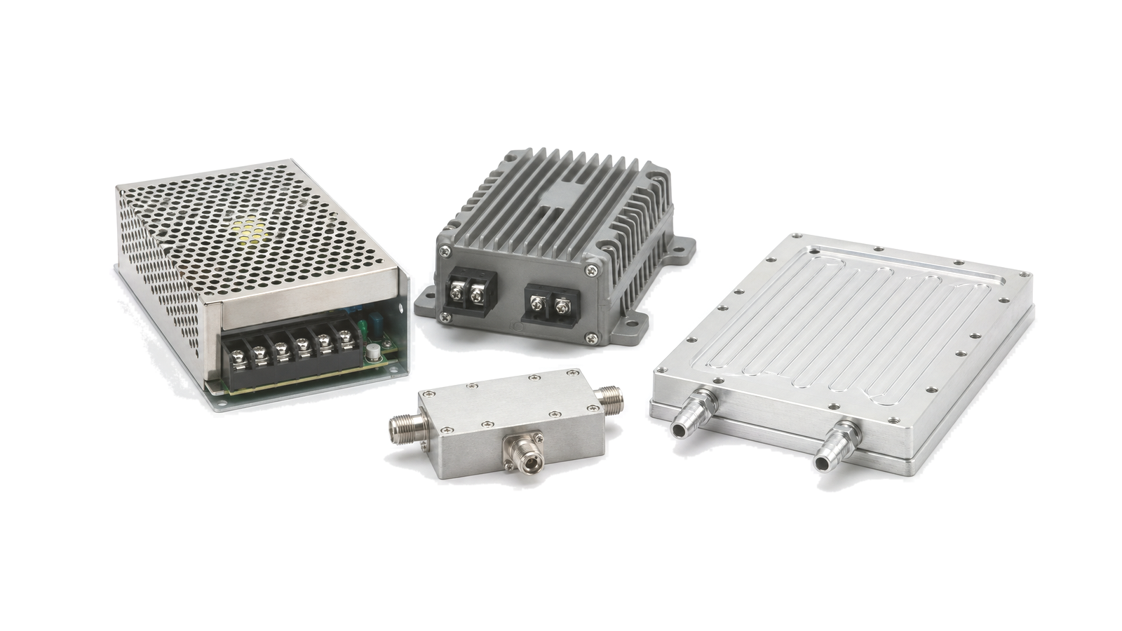
Create a rail and state table covering voltage tolerance at the module, peak and quiescent current, source impedance, cable and connector drop, inrush, current limit, ripple and noise spectrum, grounding, return path, precharge, enable timing and stored-energy discharge. Externally biased depletion-mode amplifiers may require gate bias before drain bias and the reverse order at shutdown; the correct sequence comes from the selected device or module definition, not from a generic convention. Set safe behavior for missing rails, slow ramps, controller reset, intermittent connector contact and emergency removal of RF or drain power. Confirm that protection and telemetry remain powered long enough to record the event and drive the hardware to a known state.
Model the complete heat path and preserve its mechanical assumptions
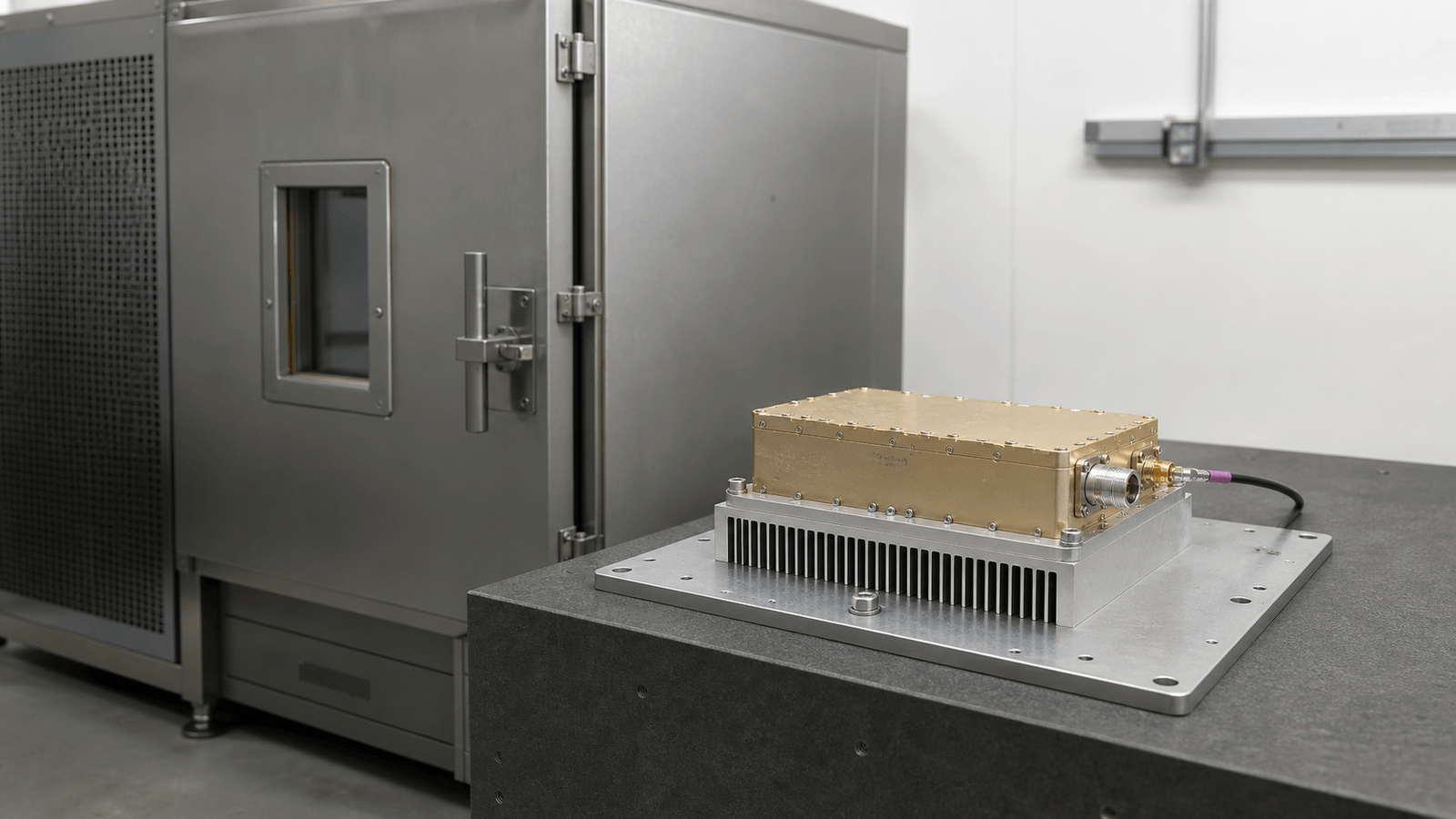
Calculate dissipated heat from measured or bounded DC input minus delivered RF output and other exported energy for every relevant operating state. Use the applicable junction-to-case or channel-to-base thermal data at its stated reference point, then add die attach, package, solder, copper, thermal vias or coin, board, interface material, flatness, clamping, baseplate, heat sink, airflow or liquid loop. For pulsed operation use transient thermal impedance or a validated dynamic model; for steady operation demonstrate equilibrium at worst ambient and cooling tolerance. Track interface thickness, contact pressure, orientation, fouling and manufacturing variation. A cold heat-sink surface does not prove a safe junction if contact resistance or a local hot spot is hidden upstream.
Make monitoring and protection observable, coordinated and recoverable
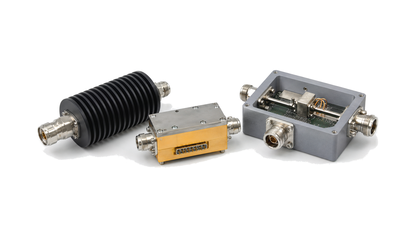
Measure variables that can support a decision: rail voltage and current, gate or drain state, baseplate or near-device temperature, airflow or coolant status, forward and reflected power, and controller health. Define sensor location, accuracy, response time, filtering and conversion to the protected quantity. Use warning, derating and shutdown thresholds with hysteresis and time qualification so normal modulation peaks do not cause nuisance trips while sustained hazards are caught. Coordinate overvoltage, undervoltage, overcurrent, overtemperature, missing cooling, excessive reflected power and oscillation responses. State whether a fault latches, retries with a limit, or requires service, and record first-fault cause rather than only the final cascade.
Turn reliability targets into derating and change-control rules
A requested lifetime or mean time between failures is not established by a part rating alone. Tie the claim to the mission profile, maximum junction or channel temperature, temperature swing, time at temperature, electrical field, current density, load mismatch, vibration and assembly interfaces. Apply design margin to temperature, voltage, current, power dissipation and cooling capability, including sensor error, model error and production spread. Select screening and qualification for the dominant risks: thermal cycling for interfaces and workmanship, powered endurance for drift or infant mortality, and combined environmental testing where the use case requires it. Reassess evidence after changes to die, package, board stack, via field, interface material, fastener torque, firmware thresholds, cooling hardware or waveform.
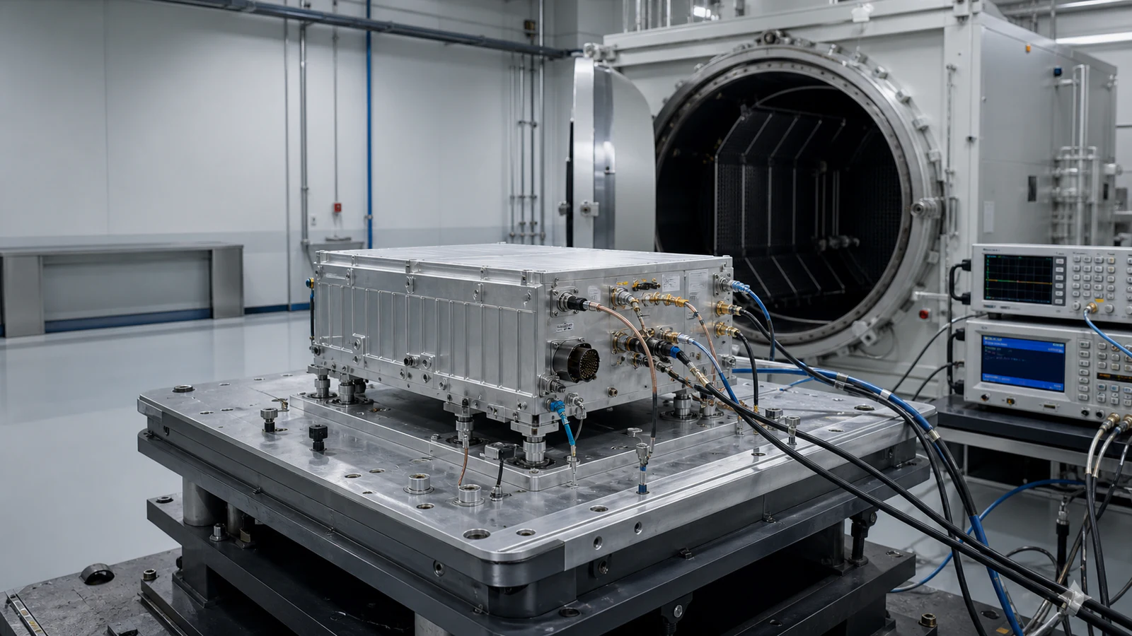
Verify electrical, RF and thermal behavior on the delivered stack
The verification matrix covers cold and hot startup, shutdown order, inrush, line and load transients, ripple sensitivity, idle and full-power dissipation, pulse and continuous operation, modulated-signal performance, gain and output drift, forward/reflected power accuracy, protection thresholds, load-mismatch magnitude and phase, cooling degradation and recovery. Instrument the supply, RF ports, reference planes, baseplate and selected thermal points with synchronized time records. Correlate thermal model and measured data under at least one stable condition and relevant transient conditions, then apply the validated model to inaccessible junction temperatures. Thermal cycling and powered endurance include functional checks during transitions and at plateaus, not only post-test survival. The report states configuration, mounting, interface material, airflow or coolant, calibration, uncertainty, limits, anomalies and disposition.
RF power and thermal verification matrix
| Operating condition | Design input | Required evidence |
|---|---|---|
| Startup and shutdown | Rail order, ramps, inrush, enable, discharge and hot restart | Synchronized voltage, current, control and fault traces |
| Rated transmit | Waveform, RF output, efficiency, ambient, cooling and duration | DC/RF balance, temperatures and stable performance |
| Pulse or burst | Pulse width, repetition, duty, burst length and recovery | Transient thermal correlation and drift |
| Load or cooling fault | Mismatch phase/magnitude, airflow/coolant loss and threshold timing | Derating, shutdown, stored fault and safe recovery |
| Life and qualification | Mission cycles, temperature swing, maximum junction, margin and change set | Cycling/endurance results and configuration-keyed rationale |
RFQ inputs for RF power, thermal and reliability engineering
- Frequency band, waveform, peak/average RF output, gain and linearity limits
- Transmit states, pulse width, repetition, duty cycle, burst and dwell profile
- Supply source, rail tolerances, peak current, cable/connector length and grounding
- Ambient, altitude/pressure, airflow or coolant inlet range and available pressure/flow
- Mounting surface, baseplate, interface material, flatness, torque and envelope
- Allowed junction/channel, case and baseplate limits with thermal data reference
- Expected VSWR or load-mismatch envelope, duration, phase coverage and recovery policy
- Required telemetry, warning, derating, shutdown, retry and fault-record behavior
- Target service life, power cycles, environmental cycles, storage and maintenance assumptions
- Qualification, acceptance, burn-in, thermal cycling, reporting and change-control requirements
Engineering boundary
The scope develops and verifies an electrical, thermal and protection architecture for a defined RF configuration and mission profile. It does not turn a component maximum rating into a guaranteed system lifetime, certify product safety, or establish reliability without representative manufacturing, environment and use data. Final limits and life claims remain conditional on the delivered hardware, cooling interface, control software, production variation and agreed qualification evidence.