
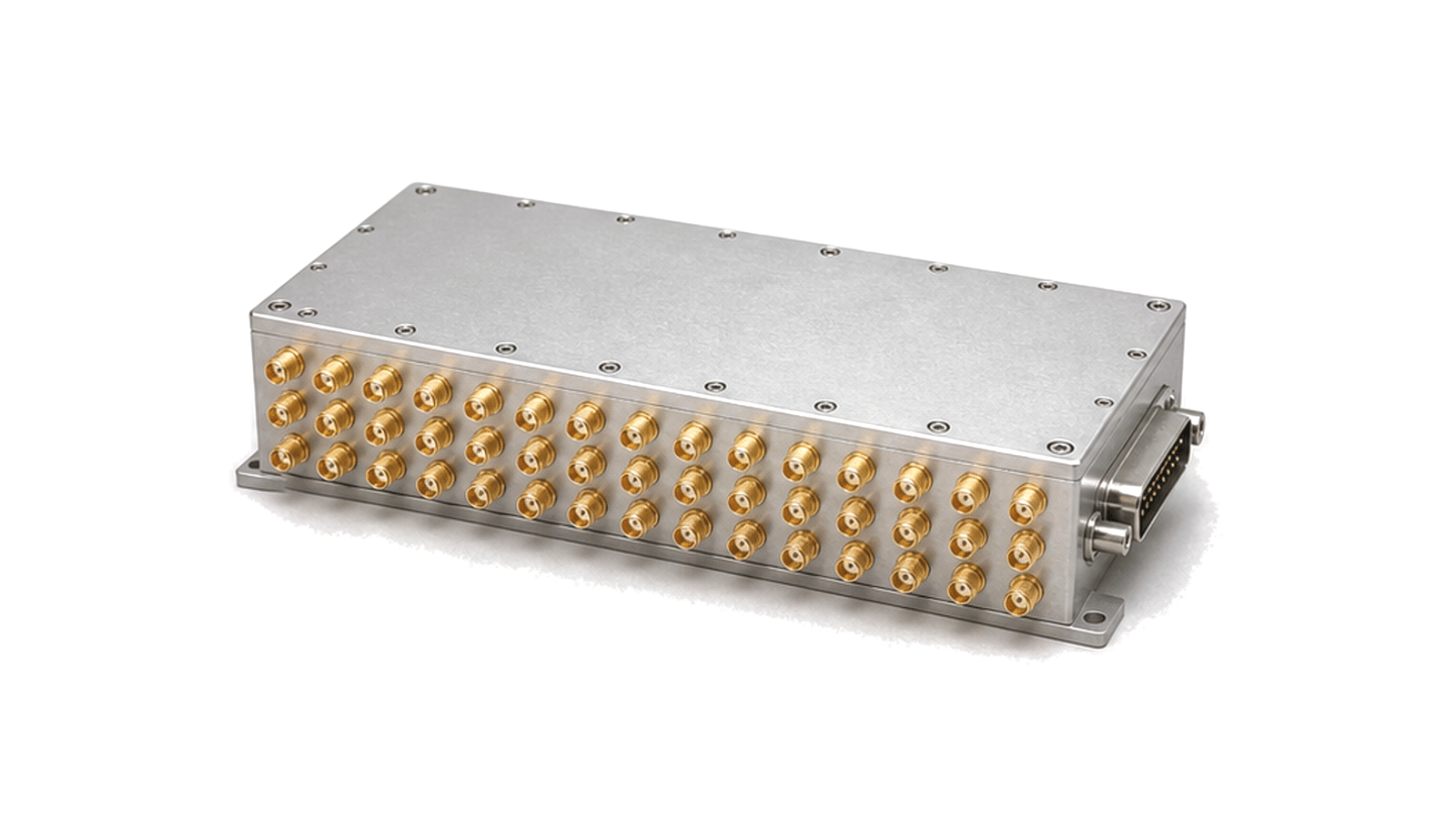
What is an RF switch matrix?
An RF switch matrix is a controlled network of RF switching elements that connects selected inputs to selected outputs without manually moving cables. It expands test-system channel count, shares instruments across devices under test and creates repeatable signal routes for characterization, production test, monitoring and receiver protection.
Define the routing topology before the port count
A port total does not describe which connections can exist at the same time. Specify matrix dimensions, blocking or non-blocking behavior, fan-out restrictions, unused-port termination, make-before-break or break-before-make sequencing and any paths that must never be connected. The route table is part of the technical specification, not merely a software detail.
Budget the complete selected path
Insertion loss, return loss or VSWR, isolation, phase stability and power handling must be stated over frequency for the complete route, including internal cables, adapters and protection components. Isolation is especially important when a high-level source and a sensitive receiver share the matrix. Hot-switch power, cold-switch power and permitted load mismatch are separate limits.
Repeatability and calibration determine measurement confidence
For automated test, a low initial loss is not enough. Review insertion-loss repeatability, switching cycles, contact-state feedback, switching time and drift with temperature. Calibrate at the matrix reference planes, store correction by route and frequency, and define when cycle count or verification data triggers maintenance.
- frequency range, impedance, connector type and matrix dimensions
- allowed simultaneous routes, termination state and switching sequence
- path insertion loss, VSWR, isolation and phase requirements
- hot- and cold-switch power, pulse conditions and load mismatch
- switching time, state feedback, control protocol and interlocks
- repeatability, rated cycles, calibration planes and acceptance report
Approval boundary
Approve the routed assembly from a measured path matrix, not from the individual switch data alone. Acceptance should identify every required route, test power, reference plane, correction method and failed-state behavior.