How should RF absorber be selected and installed?
Start with the field problem and installed acceptance metric, not with foam color or a single reflectivity number. The selection is complete only when material form, thickness, backing, incidence, power, environment and attachment are tied to a reproducible measurement. If any of those boundaries changes, the absorber must be re-evaluated in the new stack.
Name the unwanted field path before choosing a material
A chamber-wall reflection, enclosure mode, antenna-to-cable coupling path and radiometric target need different evidence. Record the source and victim, their separation, the dominant field region, the problem frequencies and the quantity that must improve. For an enclosure, that quantity may be resonance Q, receiver desense or near-field amplitude. For a range, it may be specular reflectivity at stated incidence angles.
Probe placement can disturb a small cavity, and moving a cable or lid can shift the mode. Establish a repeatable baseline before adding material. If the failure disappears when the fixture changes, the team has not yet isolated the absorber task.
Choose material family, geometry and backing as one assembly
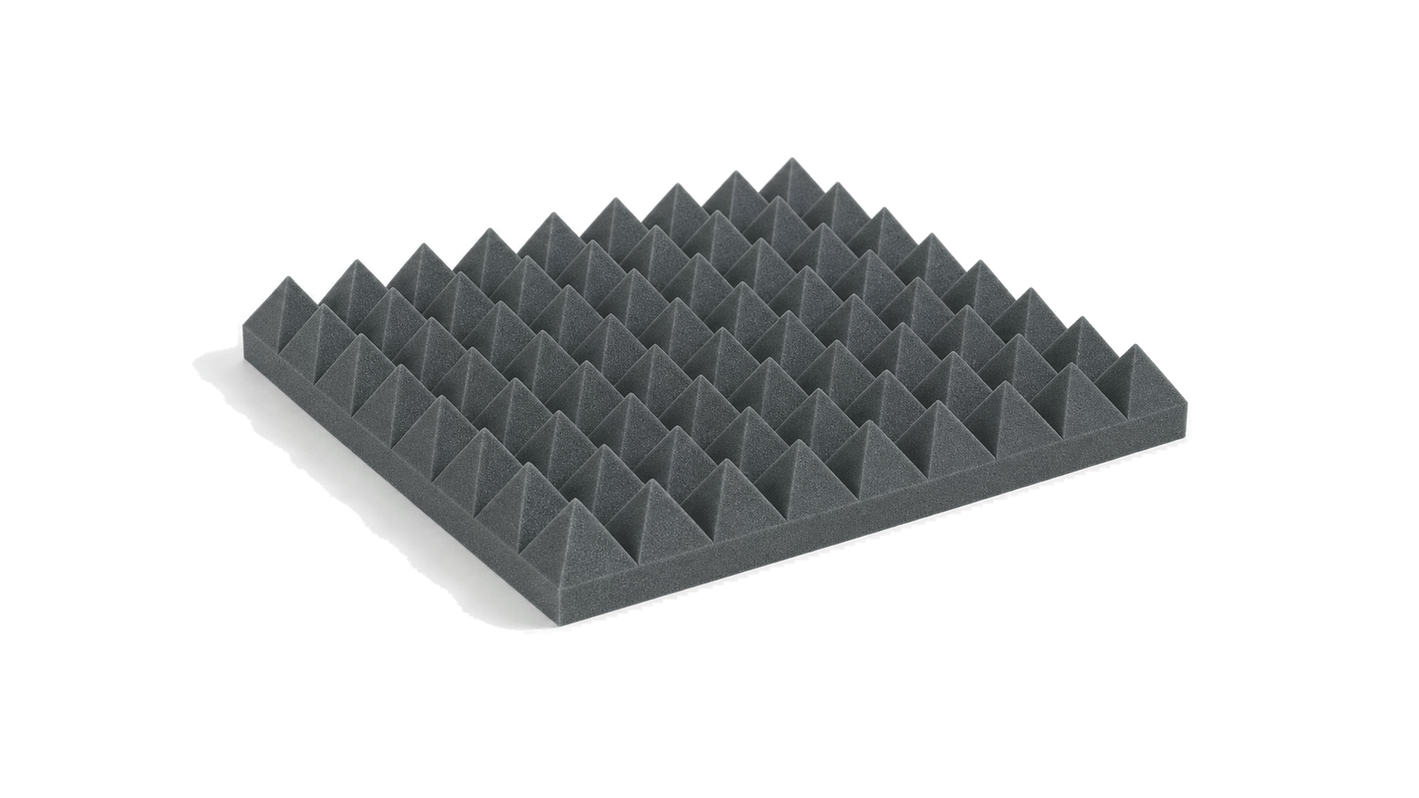
Pyramidal or wedge foam gives a gradual impedance transition and can cover broad free-space applications when depth is available. Ferrite tile is physically shallower and is often combined with dielectric absorber for wider coverage. Thin loaded elastomer, foam sheet and molded inserts fit constrained housings, but their resonant behavior and loss depend on thickness, backing conductor and local field orientation.
Do not separate the absorber from its adhesive, metal backing, coating or protective skin. A conductive backplane can be part of the intended electromagnetic stack; an unintended air layer can become a spacer. Request dimensions, density or formulation control, orientation, lot traceability and the exact test coupon construction.
Read reflectivity data with its method, angle and uncertainty
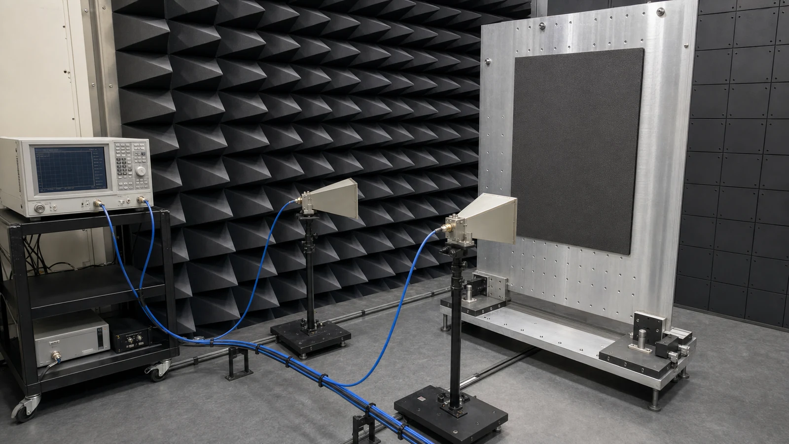
Reflectivity, return loss, transmission loss and insertion loss are not interchangeable. Free-space arch, time-gated chamber, waveguide, coaxial and fixture methods illuminate different sample sizes and mode sets. The report must state the reference reflector, calibration or normalization, antenna geometry, distance, incidence angle, polarization, time gate, frequency resolution and uncertainty.
Edge diffraction and finite sample size matter, particularly when the illuminated spot approaches the coupon boundary. A normal-incidence result does not prove wide-angle performance. Preserve the full frequency trace instead of selecting one deep minimum that disappears under another angle or polarization.
Separate RF power density, service temperature and material qualification
Absorbed electromagnetic energy becomes heat. State CW or pulsed field, average and peak power density, duty cycle, exposure duration, hot-spot location, airflow and the temperature reference used by the material limit. A short-duration maximum and a continuous rating describe different conditions; neither should be extrapolated across an unverified airflow or mounting arrangement.
Environmental acceptance may need moisture uptake, chemical compatibility, flammability, smoke, particle shedding, compression set, UV aging or vacuum outgassing. For vacuum use, TML and CVCM evidence applies to the exact material, adhesive and cure condition. Passing an RF coupon test does not qualify the assembly for fire, contamination or spaceflight use.
Treat seams, gaps, compression and adhesive as RF dimensions
Cut patterns should preserve orientation, minimum edge distance, corner fit and clearance around connectors, vents and high-voltage regions. Butt joints, open seams and exposed metal can create a reflection path. Excess adhesive, trapped air or a bowed backing plate changes the stack. In a lid, fastener pitch and compression can alter both the cavity and the material thickness.
Approve a drawing and installation process, not a hand-cut prototype alone. Record surface preparation, adhesive batch, bond-line control, cure, fastener or retaining method, allowed gap, repair limit and inspection access. Use witness samples or mass/height checks when the material can absorb moisture or take a permanent set.
Close the decision with installed before-and-after evidence
Coupon data narrows the candidate list. Qualification uses the real enclosure, chamber wall, support, cable routing and operating state. Repeat the original baseline measurement with identical reference planes, instrument state, probes and geometry. Confirm that the improvement covers the entire problem band and does not create a new hot spot or detune a wanted antenna path.
Thermal soak, power exposure, vibration, humidity or repeated lid cycling may be part of the acceptance sequence. Re-measure after the stress and after one controlled removal and replacement when maintainability matters. Retain raw data, photos of the installed stack, material lot, drawing revision and deviations.
RF absorber decision matrix
| Decision | Evidence required | Reject when |
|---|---|---|
| Field problem | Source, victim, band, field region and acceptance metric | The only input is 'reduce EMI' |
| Material stack | Form, thickness, backing, adhesive, coating and orientation | Only a trade name is supplied |
| Reflectivity | Full curve, method, angle, polarization, sample size and uncertainty | One dB point lacks a setup |
| Power | Average/peak density, duty, duration, airflow and temperature | A maximum is used as a continuous rating |
| Environment | Exact material and adhesive evidence for moisture, flame or vacuum | Generic family compliance is claimed |
| Installation | Drawing, seam/gap limit, compression, bond line and inspection | Coupon data is treated as installed proof |
Worked check: a 10 dB change is a tenfold reflected-power change
If two samples are measured in the same calibrated free-space setup and one has 10 dB reflectivity while the other has 20 dB reflectivity, the corresponding reflected-power ratios are 10% and 1%. The second sample returns one tenth as much power under that setup. The comparison is valid only for the same frequency, angle, polarization, backing, illuminated area and time-gating method; it does not by itself establish power handling or the result inside an enclosure.

Verification sequence from coupon to installed assembly
- Record the source, victim, problem frequencies, field region and baseline metric.
- Freeze sample dimensions, material lot, thickness, orientation, backing, adhesive and conditioning.
- Use a stated free-space, waveguide, coaxial or fixture method with calibration and uncertainty.
- Measure the full band at required incidence angles and polarizations, retaining raw complex data where available.
- Apply declared CW or pulsed power density while monitoring the relevant hot spot and airflow.
- Install to the controlled drawing and inspect seams, corners, gaps, compression and exposed metal.
- Repeat the original system measurement with unchanged cable, probe, lid and instrument references.
- Re-test after thermal, humidity, vibration, vacuum or maintenance stress required by the project.
- Archive raw data, configuration photographs, lot, cure, drawing revision and acceptance deviations.
Failure modes that make attractive absorber data unusable
- Selecting from one best-case reflectivity value without the measurement geometry
- Using a normal-incidence coupon to claim oblique or near-field performance
- Ignoring the conductive backing, adhesive bond line or trapped air gap
- Treating short-duration power as a continuous rating
- Qualifying the absorber but not the adhesive for flame, vacuum or chemicals
- Leaving seams, corners or connector cutouts as reflective paths
- Changing probe, cable or lid position between baseline and final measurement
- Assuming a lower chamber reflection automatically cures an internal cavity mode
RF absorber RFQ and test inputs
- Unwanted field path, operating state, frequency intervals and required reduction
- Free-space, chamber, cavity, near-field or aperture application
- Incidence angle, polarization and reference measurement method
- Available area, depth, mass, backing metal and keep-out dimensions
- Material form, thickness tolerance, orientation, adhesive and protective coating
- Average and peak field or power density, duty, duration, airflow and temperature
- Humidity, chemicals, UV, flame, smoke, particle and vacuum/outgassing limits
- Seam, corner, gap, compression, fastener and repair acceptance limits
- Coupon, lot, installed before/after and post-stress evidence to be delivered