
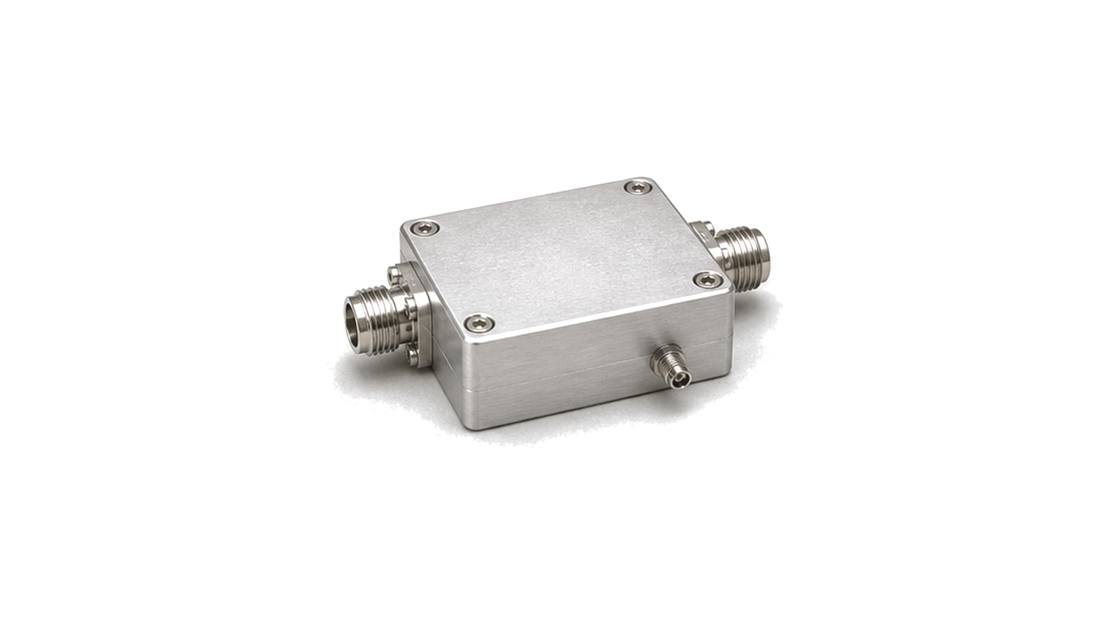
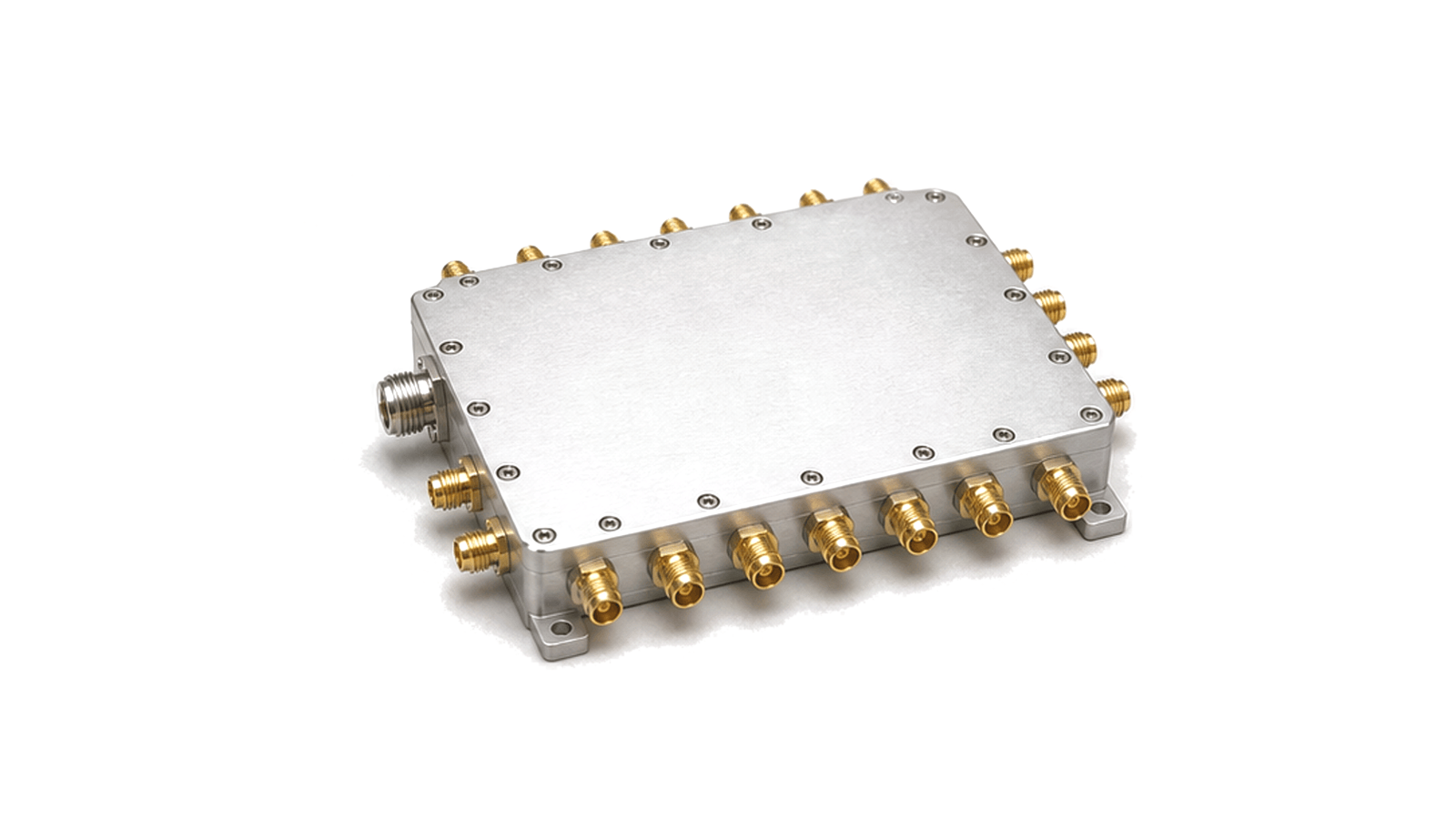
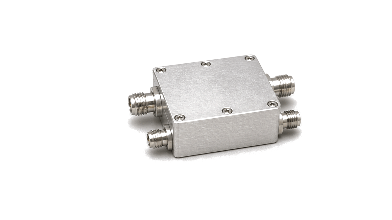
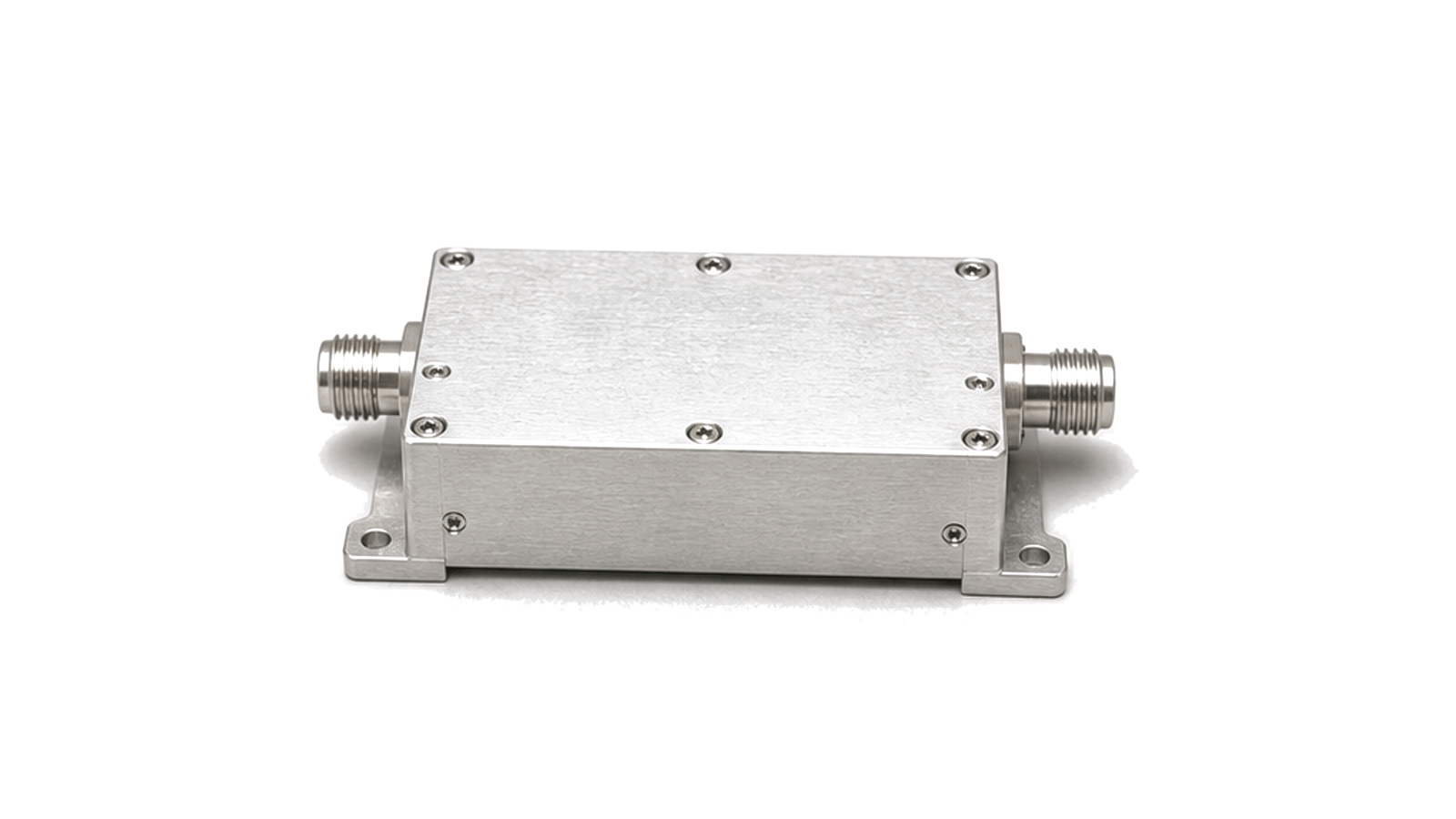
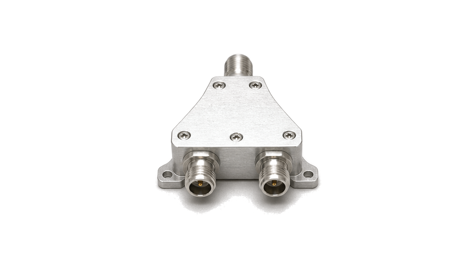
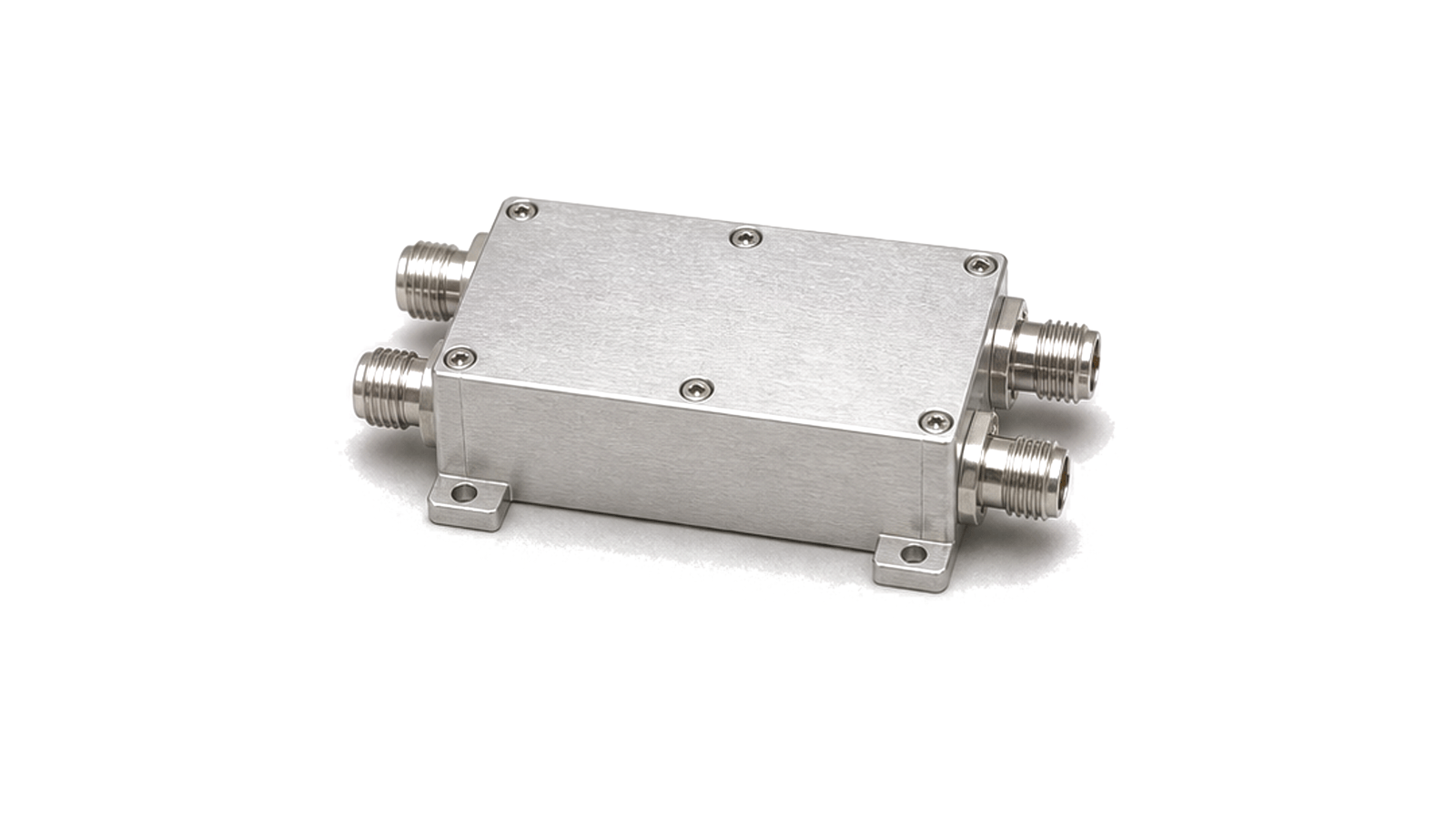
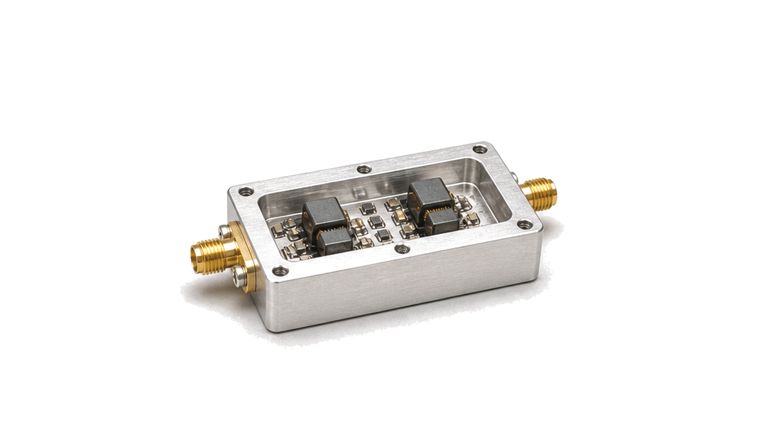
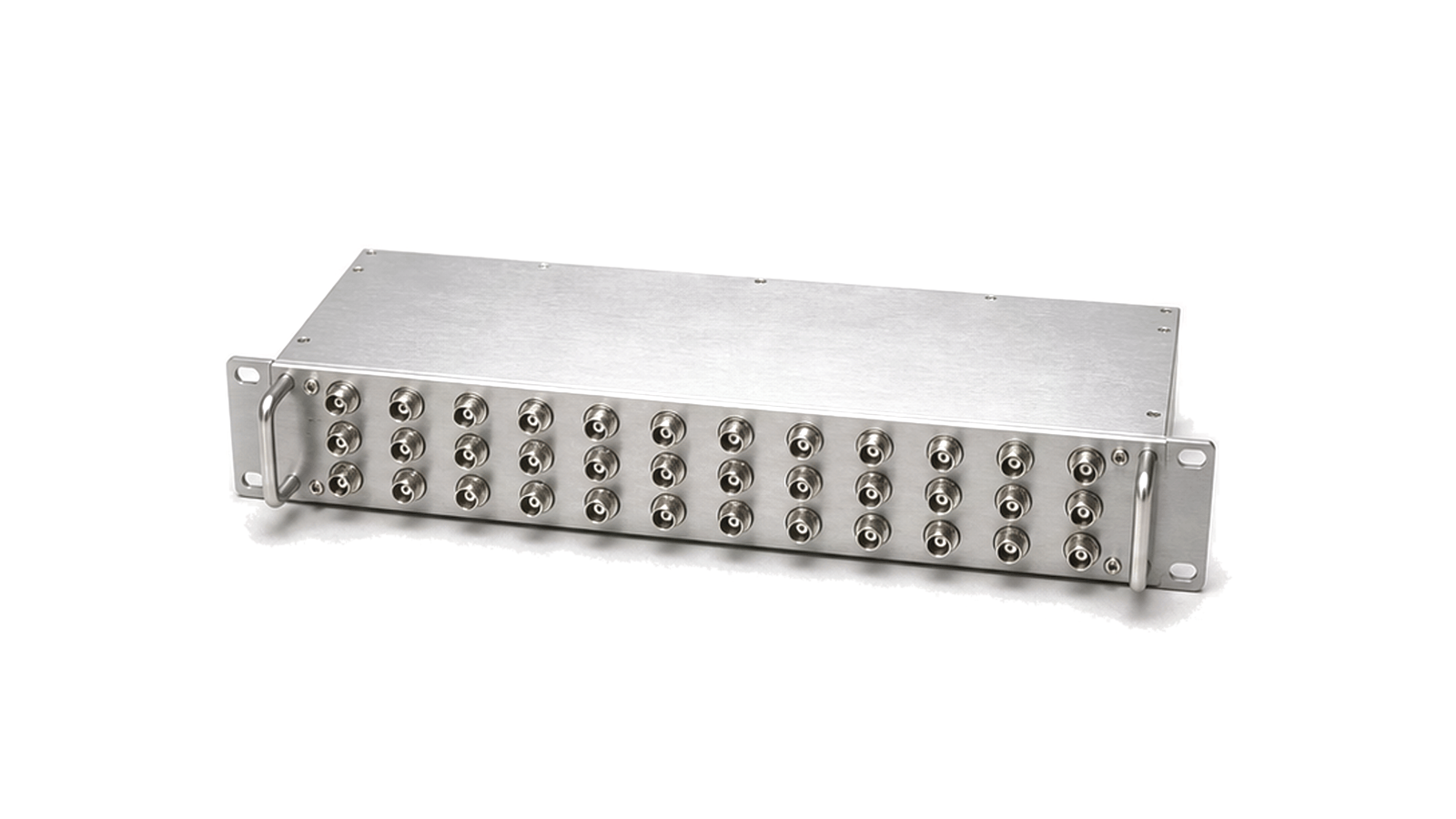
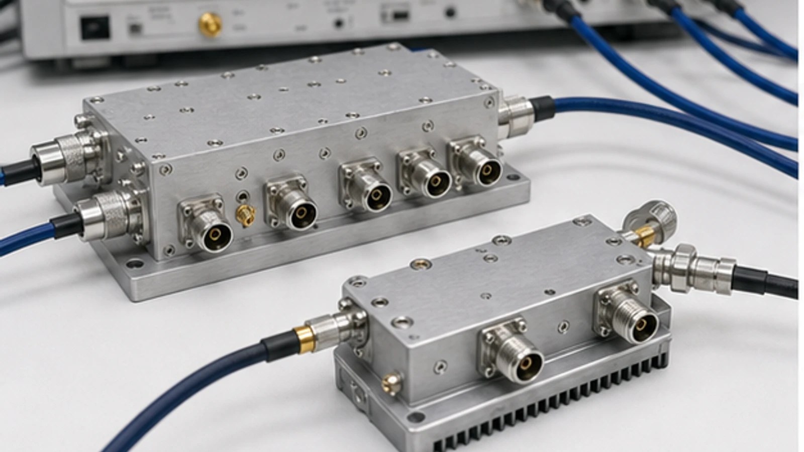
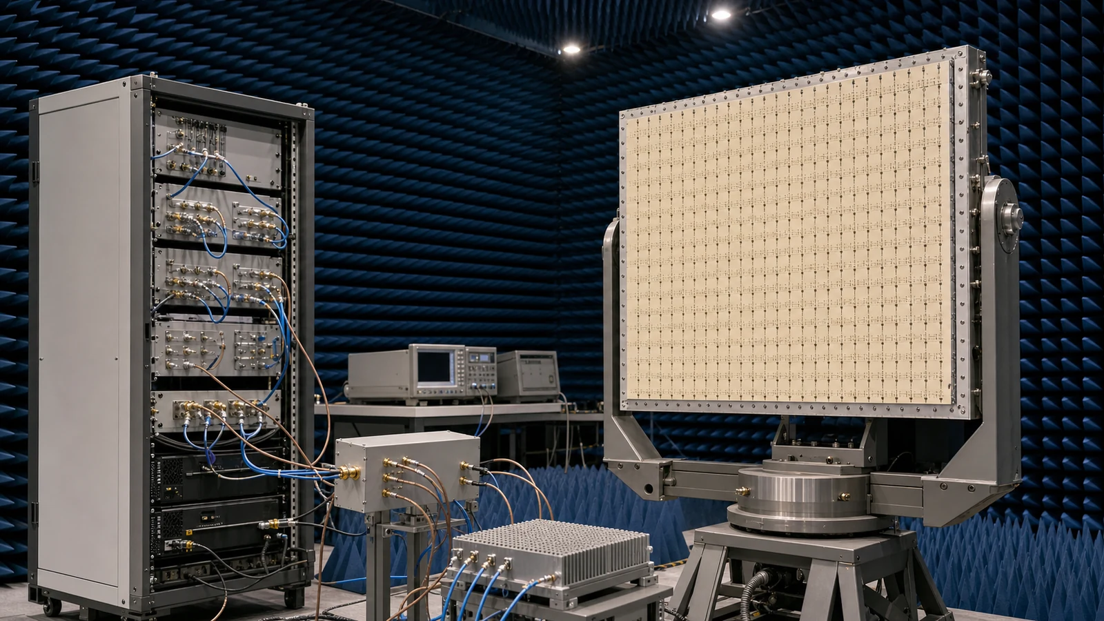
What is RF power distribution, combining and coupling?
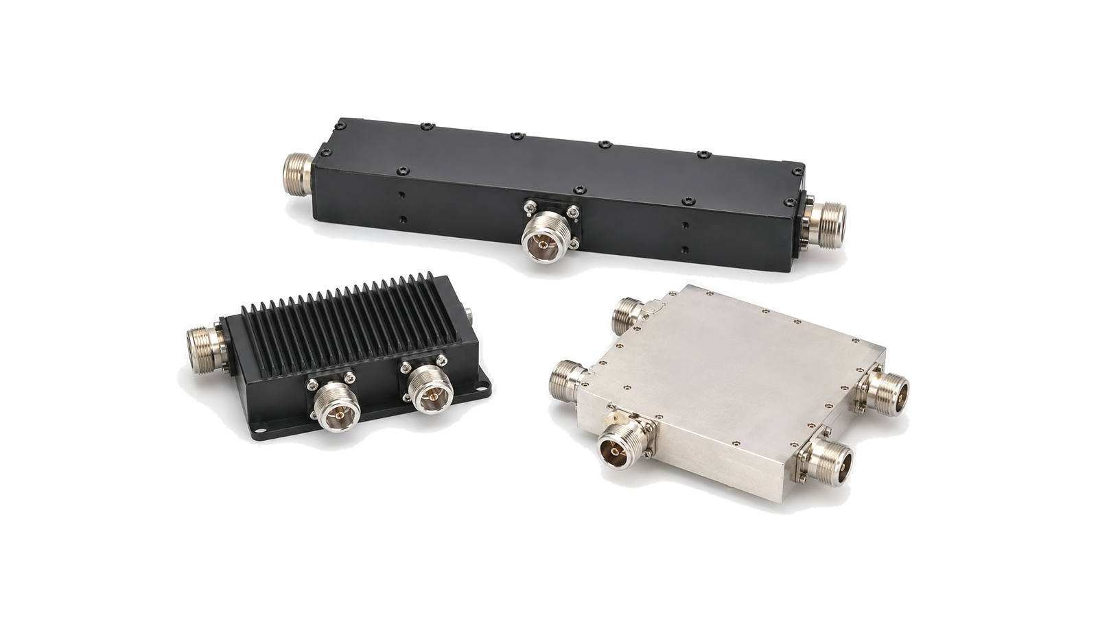
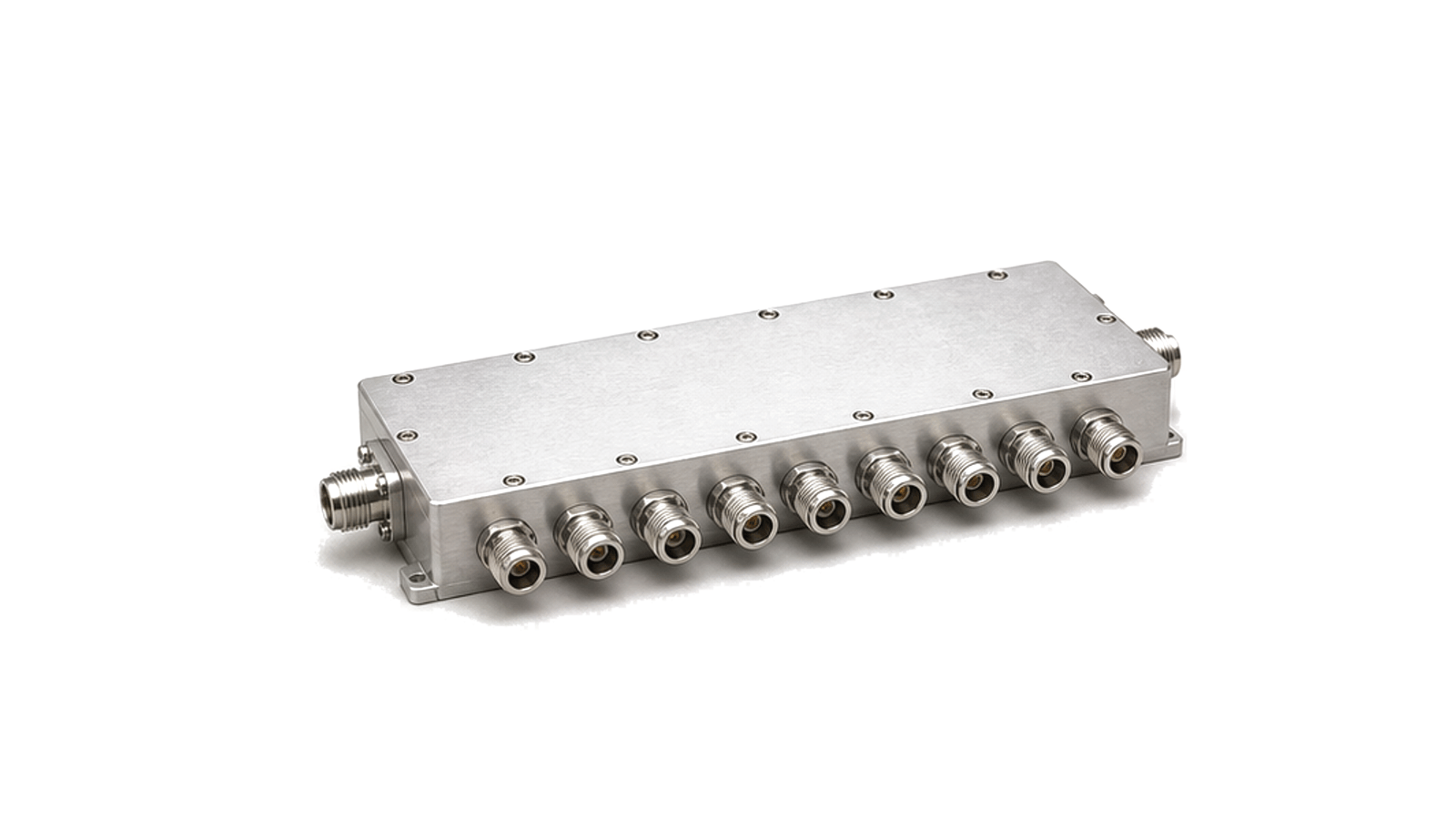
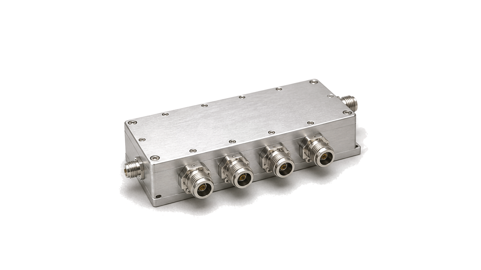
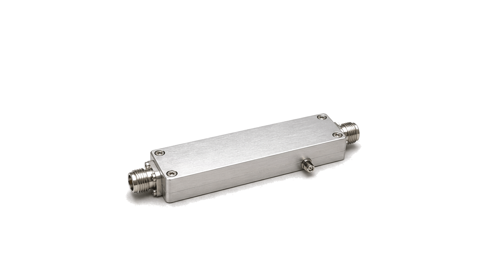
RF power-distribution hardware divides one signal into controlled paths, combines compatible paths into one output, or samples part of a travelling wave without replacing the main through path. Power dividers, combiners, directional couplers, hybrids, baluns and distribution assemblies differ in topology and purpose. Selection starts with port function and signal direction, then moves to loss, isolation, balance, directivity, power and mechanical integration.
How do you select a divider, combiner or coupler?
Draw the network with named source, load and measurement ports. State whether power flows one way or can be reflected, whether paths carry coherent signals, and whether the network is used for distribution, combining, monitoring or protection. Set the frequency band and impedance, then calculate the available loss and power margin at each port. For coherent combining, amplitude and phase errors must be budgeted with the upstream amplifiers and interconnect.
| Hardware family | Primary purpose | Critical checks |
|---|---|---|
| Power divider or combiner | Create or recombine controlled signal paths | Insertion loss, isolation, amplitude and phase balance, port match and power rating |
| Directional coupler | Sample forward or reflected power while preserving a through path | Coupling factor, directivity, flatness, main-line loss and coupled-port power |
| Hybrid | Create defined phase relationships between ports | Phase balance, amplitude balance, isolation and termination condition |
| Balun or transformer network | Convert balanced and unbalanced interfaces or transform impedance | Balance, common-mode behavior, insertion loss, bandwidth and power |
Which technical specifications matter?
Insertion loss must be separated from theoretical splitting loss. Port return loss and isolation show how strongly connected paths can interact. Directional couplers add coupling accuracy and directivity; hybrids add phase balance; combiners add dissipation under unequal amplitude, phase or load conditions. Average power, peak power, connector limits, temperature rise and mismatch exposure should be specified together.
Mechanical layout can be an RF parameter. Connector orientation, cable bend, mounting flatness, housing contact and thermal path affect repeatability and power handling. At higher frequencies, fixture and adapter transitions can contribute enough loss or mismatch to distort the apparent device result, so reference planes and de-embedding must be defined.
Evaluating an RF distribution supplier or manufacturer
Ask for data across all relevant ports and the full operating band, not only a representative trace. Confirm the termination conditions used for isolation, directivity and balance measurements. For high-power networks, request the assumptions behind power ratings, including ambient or baseplate temperature, duty cycle, altitude, cooling and mismatch. Production acceptance should identify the ports and limits measured on each unit.
How is RF power-distribution hardware tested and verified?
A vector network analyzer can measure insertion loss, return loss, isolation, coupling and phase across the required ports. Power testing then verifies temperature rise, compression, connector behavior and stability under the intended CW, pulsed or modulated signal. Combining networks should be checked under amplitude and phase imbalance as well as nominal conditions. Couplers used for monitoring need forward and reflected calibration against the system reference planes.
- Port count, function, impedance and signal direction
- Frequency band and allowed insertion or splitting loss
- Isolation, amplitude balance, phase balance or directivity
- Coupling factor and coupled-port power where applicable
- Average, peak and reflected-power conditions
- Connector, outline, mounting and thermal interface
- Environmental and lifecycle requirements
- Per-port acceptance limits and calibration records
Selection and approval boundary
This category defines the available network functions and comparison evidence; it does not establish a power rating for a specific model. Final approval requires port-level RF data and power evidence under the project's load, waveform, mounting and temperature conditions.