Treat the complete physical path as the controlled measurement hardware
A defensible specification names every transition between the instrument port and the DUT, then decides which transitions are calibrated, characterized, de-embedded or left in the reported result. Calibration kits, cables, adapters, switches, probes and fixtures can each add mismatch, loss, phase shift, leakage and repeatability error. Buying each item by frequency range alone does not create a repeatable measurement chain.
Define the measurement task and the hardware boundary
Begin with the measurand and the DUT interface, not with an accessory catalog. A connectorized two-port module, a PCB coupon, a wafer device and a high-power assembly impose different calibration, fixturing, contact and protection needs. State whether the path supports S-parameters, power, noise, gain, compression, monitoring or a production decision, because source level, receiver dynamic range, linearity and damage limits change with the task.
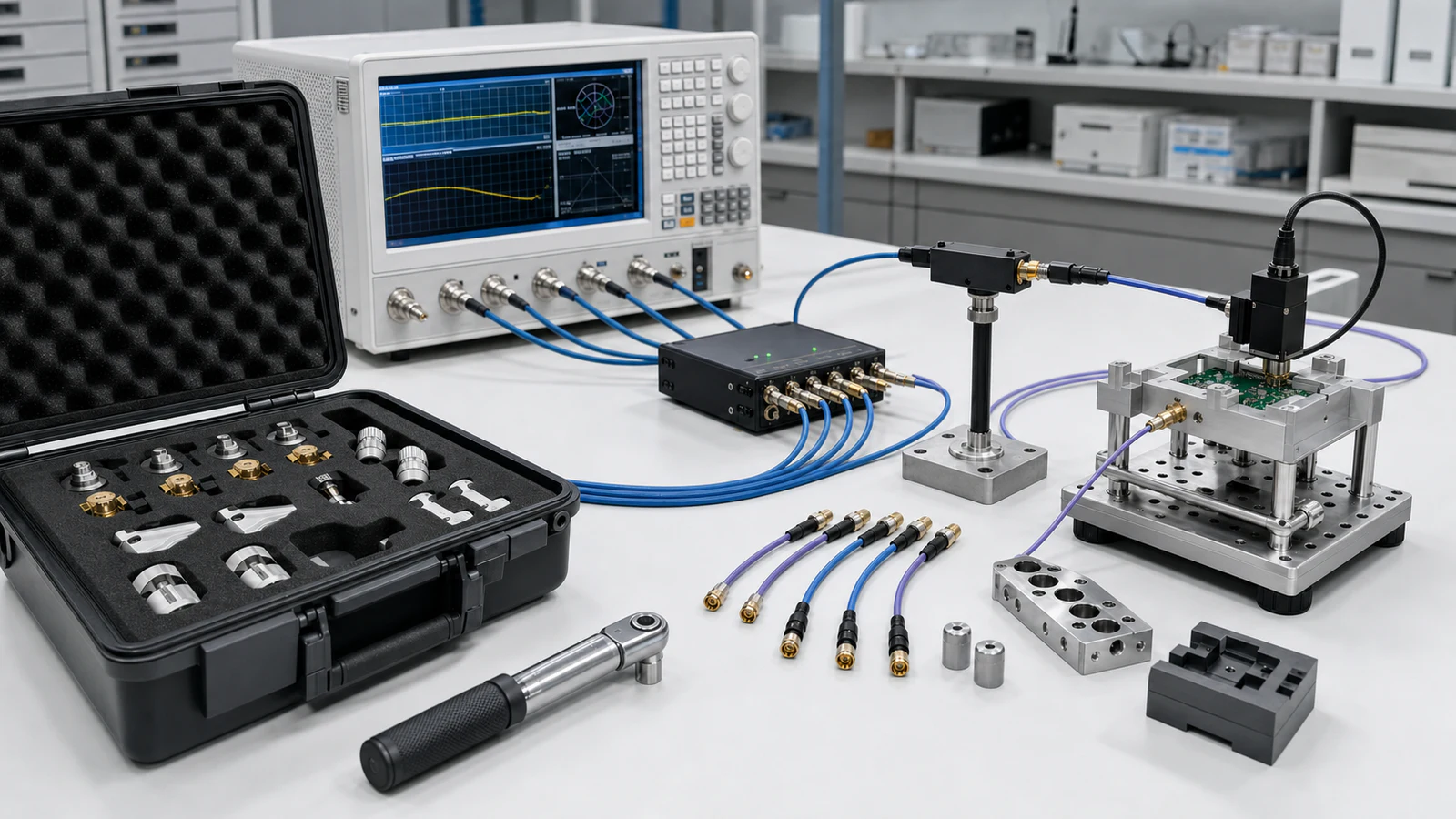
Draw the physical chain from the instrument test port through cables, adapters, bias or protection elements, switch matrices, fixtures and probes to the DUT. Mark every connector, switch state and mechanical datum. This article owns the hardware path; the full component-characterization plan, instrument selection and production automation remain separate engineering decisions.
Freeze the DUT interface and corrected reference plane
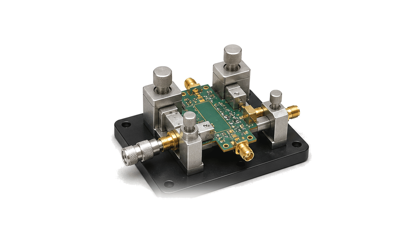
Name the interface by connector series, gender, impedance, waveguide flange, PCB launch or probe geometry. For fixtures, define substrate, launch, transmission-line geometry, grounding, clamping and mechanical datum. For probes, define pitch, pad geometry, contact force, planarity, touchdown limit and cleaning practice. The delivered interface must match the model used during calibration or fixture characterization.
State where corrected data will be reported. If the plane is at the instrument port, every downstream element remains in the result. If it is moved to a fixture connector, probe tip or DUT pad, the intervening path needs calibration, port extension or a validated de-embedding model. Do not use the phrase 'at the DUT' without a drawing or datum that another laboratory can reproduce.
Match the calibration kit, standard definitions and method
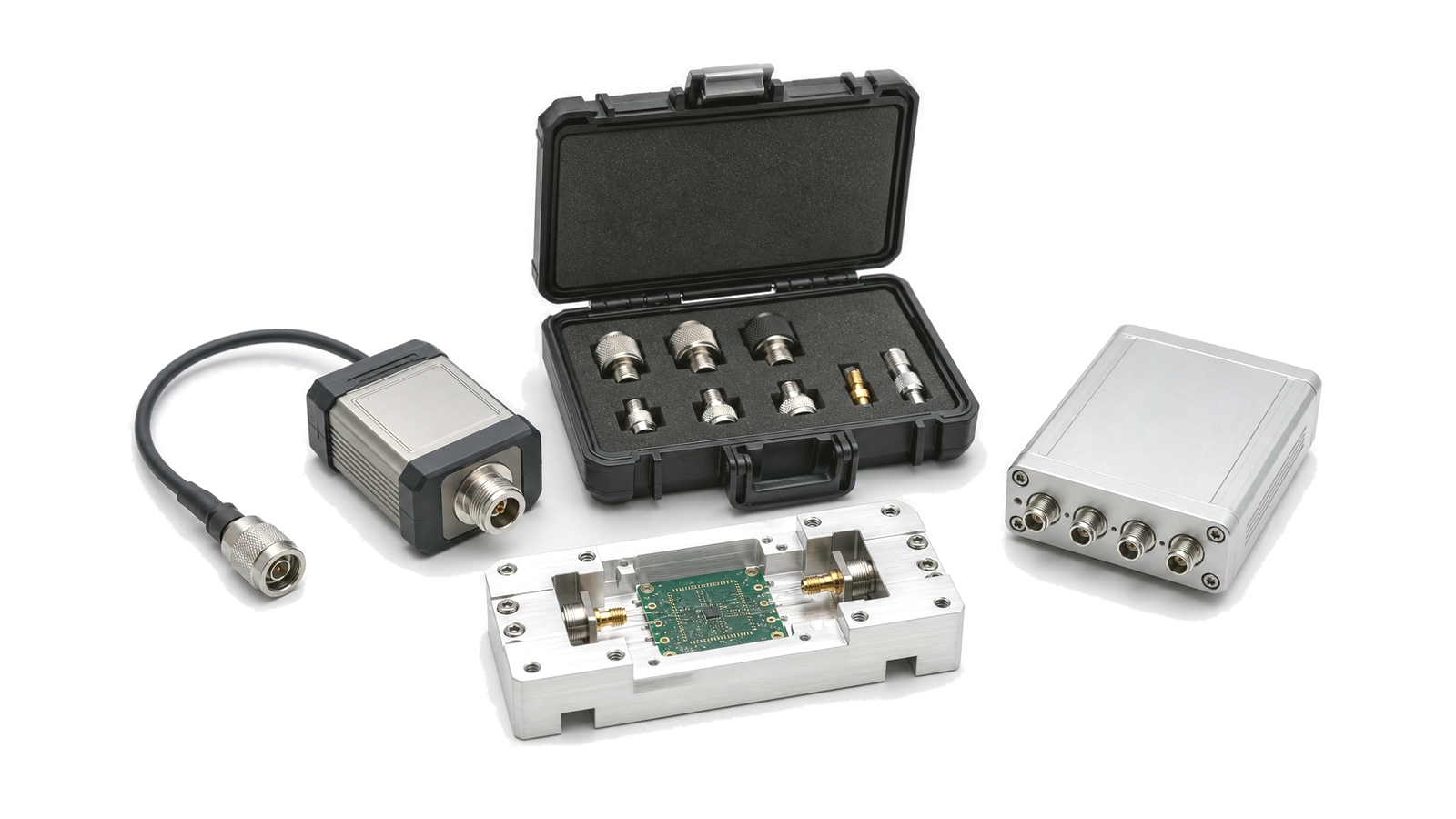
Select a calibration method compatible with the number of ports, connector or probe interface, frequency range and required accuracy. The physical open, short, load, through, line, reflect or electronic calibration module must correspond to the kit definition loaded by the instrument. Standard class, delay, loss, offset impedance and coefficient data are not administrative details; a wrong definition embeds systematic error into every corrected result.
Record kit identity, serial numbers, connector type and sex, usable frequency range, definition-file revision, calibration certificate, environmental condition and inspection status. A certificate supports the artifact's calibration history, but traceability belongs to the measurement result and requires a documented chain, uncertainty contributions, correct use and internal measurement assurance.
Allocate cables, switches, probes and conditioning by path state
Phase-stable cables still change with bend radius, torsion, temperature and connector remating. Define routing, minimum bend radius, strain relief, flexure during use, insertion and return-loss limits, phase-with-flexure where relevant and a periodic cable check. Adapters should be minimized and identified by position; replacing one after calibration changes the path even when the connector family appears equivalent.
For a switch matrix, specify every routed state, unused-port termination, isolation, insertion loss, repeatability, power handling, hot-switch restrictions and simultaneous-signal condition. For signal-conditioning hardware, include gain or loss, compression, noise, DC blocks, bias paths, limiting and protection. For probes and fixtures, include contact repeatability and the mechanical state that must be recreated after maintenance.
Control connector condition, torque, alignment and wear
Inspect, clean and gauge precision interfaces before damage is transferred to a mating standard or test port. Use the specified torque tool while preventing the connector body from rotating. Record pin-depth or interface-gauge failures, contamination, dents, cross-threading and unusual mating force. A connection that can be tightened is not necessarily a metrologically usable connection.
Measure remate repeatability on representative standards or stable devices. Fixtures also need repeatable clamp force, board seating, ground contact, fastener sequence and probe touchdown. Establish mating-cycle, touchdown, cleaning and replacement limits before the path becomes a production dependency; otherwise gradual wear is discovered only after correlation fails.
Separate calibration records, traceability and measurement uncertainty
The accessory file should connect physical identity to the correction data used with it. Retain calibration method, kit and standard identity, instrument and cable path, fixture or probe revision, raw Touchstone data, de-embedding files, environmental conditions, operator-independent setup instructions and uncertainty inputs. Screenshots are useful for orientation but cannot replace native data and configuration history.
Traceability is not a sticker on a calibration kit. It is a property of the reported result through a documented chain of calibrations, each contributing uncertainty. Add internal checks that can reveal path drift, cable damage, switch-repeatability change or connector wear. If the project requires accredited or customer-specific records, name that requirement explicitly rather than inferring it from a supplier certificate.
Use check standards and lifecycle triggers between calibrations
Choose an independent check standard that is stable, sensitive to important error terms and not used to create the calibration being checked. Measure it after calibration, after a questionable remate, after cable movement, after a fixture or switch change and at a controlled interval. Compare complex data or bounded metrics against a baseline with defined warning and failure limits.
Time alone should not determine every interval. Add triggers for mating count, probe touchdowns, cable flexure, switch cycles, temperature excursion, overload, dropped hardware, failed gauge, failed check standard and correlation drift. Quarantine the affected path when a limit is exceeded, identify the last known valid check and assess which prior DUT results may need review.
| Decision boundary | Requirement to freeze | Reject the proposal when |
|---|---|---|
| DUT interface | Connector, flange, PCB launch, probe geometry and mechanical datum | The interface is described only as connectorized or on-wafer |
| Reference plane | Reported plane and every included, calibrated or de-embedded transition | The phrase at the DUT has no reproducible drawing |
| Calibration hardware | Method, kit definition, standards, serials, frequency and correction-file revision | A generic kit name is supplied without matching definitions |
| Cables and adapters | Routing, bend, strain relief, phase stability, return loss and remate controls | Any equivalent cable or adapter may be substituted after calibration |
| Switching and conditioning | Path states, isolation, repeatability, linearity, power and protection | Only the best insertion-loss path is documented |
| Fixture or probe | Geometry, launch, clamping, contact, cleaning and lifecycle limits | Mechanical setup cannot be recreated by another operator |
| Measurement assurance | Check standard, baseline, limits, interval and event-based triggers | Calibration completion is treated as the only quality check |
| Records | Native data, uncertainty inputs, traceability chain, serial, revision and change history | Only a certificate or screenshot is retained |
Worked decision: moving the plane to a fixture connector does not remove the fixture
Assume a VNA is calibrated at the ends of two phase-stable cables, while the DUT sits behind a switch path, adapter and PCB fixture. The calibration corrects the instrument and cable path only. The switch, adapter, launch and fixture remain in the measured result unless they are included in a different calibration or removed with a validated model. A useful procurement specification therefore identifies the routed switch state, adapter part and orientation, fixture revision, characterization file, connector torque, board-clamp sequence and check-standard limits. Calling the result 'DUT S-parameters' without these boundaries hides the dominant repeatability risk.

Verify the path from standard identity to DUT-plane repeatability
- Approve the measurand, DUT interface, continuous frequency range, source level, receiver range and damage limits.
- Freeze the physical path drawing, connector sexes, adapters, cable routing, switch states, fixture or probe geometry and mechanical datums.
- Confirm that physical calibration standards match the selected method, kit definition and correction-file revision.
- Inspect, clean, gauge and torque interfaces using controlled tools and record any failed condition.
- Calibrate at the declared plane and save calibration identity, settings, environmental condition and operator-independent setup record.
- Characterize or de-embed only the transitions supported by a validated model and retain the native files and validation result.
- Measure an independent check standard and compare complex response or bounded metrics with the approved baseline.
- Test cable flexure, connector remate, fixture reload, probe touchdown and switch-state repeatability where they affect the result.
- Recheck after maintenance, overload, impact, temperature excursion, failed gauge, failed verification or hardware revision.
- Retain serials, revisions, raw data, correction files, uncertainty inputs, acceptance result and the last known valid check.
Measurement-path failures hidden by an accessory list
- Selecting a calibration kit by connector family without matching its standard definitions
- Reporting at the DUT while leaving an uncharacterized fixture inside the result
- Replacing an adapter, cable or switch path after calibration without re-verification
- Treating phase-stable cable as insensitive to bending, torsion, temperature or remating
- Using damaged, contaminated or ungauged connectors because they still mate
- Specifying switch-matrix insertion loss without state repeatability, isolation or power conditions
- Ignoring probe contact force, touchdown count, pad wear or fixture clamp sequence
- Calling a measurement traceable because one artifact has a calibration certificate
- Accepting screenshots without raw data, correction files, configuration and uncertainty inputs
- Assuming every taxonomy family represents an immediately available production model
Information required for an RF test fixture and calibration-hardware RFQ
- Measurement task, DUT type and engineering decision the path must support
- Continuous frequency range, impedance, source power, receiver level and dynamic-range requirement
- DUT connector, flange, PCB launch, probe pitch, pad geometry and mechanical datum
- Reported reference plane and list of transitions included, calibrated, characterized or de-embedded
- Calibration method, port count, calibration-kit model or definition and standard classes
- Required serial identity, coefficient files, certificate, traceability and uncertainty records
- Cable length, routing, flexure, bend radius, strain relief, phase and return-loss limits
- Adapter positions, connector sex, pin depth, torque, gauge and mating-cycle controls
- Switch-matrix topology, path states, unused-port condition, isolation, repeatability and power limits
- Signal-conditioning gain or loss, compression, noise, DC, bias, limiting and protection boundaries
- Fixture geometry, substrate, launch, grounding, clamping, fastener sequence and revision control
- Probe geometry, contact force, planarity, cleaning, touchdown and replacement limits
- Check standard, baseline, warning or fail limits, interval and event-based re-verification triggers
- Sample quantity, first-article evidence, native data, spares, maintenance and change control