What makes a coaxial RF surge protector installation acceptable?
Acceptance requires the correct topology at the protection-zone boundary, a short low-inductance bond and a retained electrical baseline before exposure. The device label or a continuity check is insufficient. Record the exact protector and cartridge revision, mounting and earth path, connector torque and sealing, S11, S21, DC pass or block, insulation and PIM where applicable. After a severe event, compare the same measurements and replace when the maker's inspection, sparkover, leakage, RF or mechanical limit is not met.
Create a commissioning baseline that can support a post-event decision
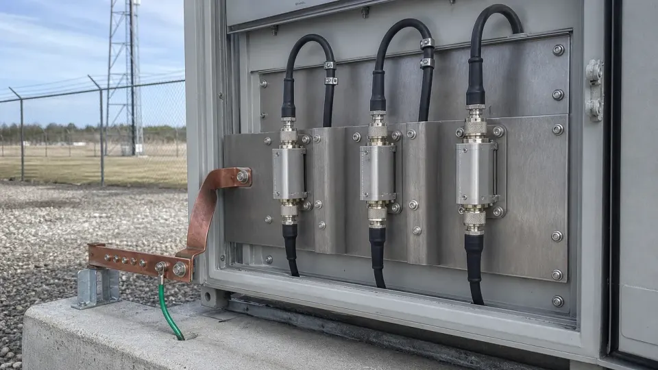
Photograph both cable sides, the bulkhead bond and the final weather seal; record serial or cartridge identity, port direction, connector torque, bonding conductor geometry and site earth point. Measure the protected path with the final jumpers in place and save native VNA data, DC continuity or isolation, remote-power current and PIM where required. A later inspection can only distinguish damage from normal variation when reference planes, adapters, frequency grid, test power, cable state and ambient conditions remain identifiable.
Compare protection topology and impulse data on the same basis
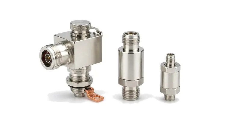
Gas-discharge-tube protectors are broadband and may pass DC, but their static and impulse sparkover, follow-current behavior, cartridge life and residual energy require coordination with the equipment port. Quarter-wave or shorting-stub designs can offer low residual voltage in a defined RF band, but bandwidth and DC behavior depend on the mechanical filter. Hybrid stages add finer clamping at the cost of more topology-specific limits. Compare nominal discharge current only when the waveform is identical: an 8/20 microsecond induced-surge rating is not interchangeable with a 10/350 microsecond partial-lightning-current rating. Also compare impulse sparkover, residual voltage, RF power, VSWR, insertion loss, PIM, environmental seal and replaceability.
Install at the bond boundary and verify after stress
Use a conductive bulkhead or the shortest specified ground connection at the cable entry; a long pigtail adds inductive voltage exactly when surge current rises fastest. Keep protected and unprotected cable routes separated, respect port direction where specified, weather-seal the exposed interface, apply connector and mounting torque, and avoid cable strain. Coordinate the coax protector with antenna bonding, feeder grounding kits, mains and data-line SPDs and any downstream receiver limiter. Before service, record S11, S21, DC continuity or isolation and PIM where relevant. After a severe event, inspect for arcing, heat or connector damage and repeat breakdown or cartridge, return-loss and insertion-loss checks under the maker's procedure.
Commissioning and post-event decision matrix
| Boundary | Commissioning evidence | Retest or replacement trigger |
|---|---|---|
| Protection zone | Protector at the exposed-to-protected boundary; separated cable routes | Bypass path, remote mounting or mixed protected and exposed routing |
| Bonding | Conductive bulkhead or shortest approved low-inductance bond | Loose, corroded, heated or mechanically altered bond |
| RF path | Saved S11 and S21 over operating and guard bands | Shift beyond the approved uncertainty and limit |
| DC and control | Pass/block, insulation, bias voltage and current verified | Leakage, open circuit, unintended conduction or unstable remote power |
| Impulse element | Exact GDT, quarter-wave or hybrid revision and maker test method | Failed sparkover/leakage check, exhausted cartridge or unknown history |
| Mechanical seal | Torque, strain relief, weather seal and connector condition | Arc mark, carbon track, water ingress, heat or connector deformation |
Worked check: a long ground lead can dominate the residual voltage
For an illustrative current rise of 1 kA per microsecond, only 1 microhenry of connection inductance produces about 1 kV from V=L·di/dt before device residual voltage is added. The example is not a lightning-current rating; it shows why a protector with strong impulse data can still fail at a site when mounted through a long pigtail instead of a bonded bulkhead.

Commissioning and post-lightning verification sequence
- The device label or a continuity check is insufficient. Record the exact protector and cartridge revision, mounting and earth path, connector torque and sealing, S11, S21, DC pass or block, insulation and PIM where applicable. After a severe event, compare the same measurements and replace when the maker's inspection, sparkover, leakage, RF or mechanical limit is not met.
- Confirm the protected-side equipment is isolated before any maker-approved sparkover or insulation test.
- Compare post-event results with the same reference planes and uncertainty; do not return the path to service solely because it still passes RF.
Installation and maintenance failures that defeat the rating
- Protector installed far from the cable entry
- Long coiled ground pigtail used instead of a bonded bulkhead
- Protected and unprotected feeders routed together
- DC pass/block or remote-power current never verified
- Impulse current values compared across different waveforms
- Connector adapters added after baseline measurement
- No cartridge, serial or event history retained
- RF continuity used as the only post-lightning test
Commissioning record and service inputs
- Protection-zone boundary, exposed feeder route and equipotential bond point
- Connector, impedance, frequency band, insertion loss, return loss and PIM
- Peak RF power, maximum line voltage, DC pass or block and control current
- GDT, quarter-wave, hybrid or other topology with stated residual behavior
- Impulse current and voltage ratings with their exact 8/20 or 10/350 waveform
- Bulkhead grounding, sealing, service access and post-event retest plan