
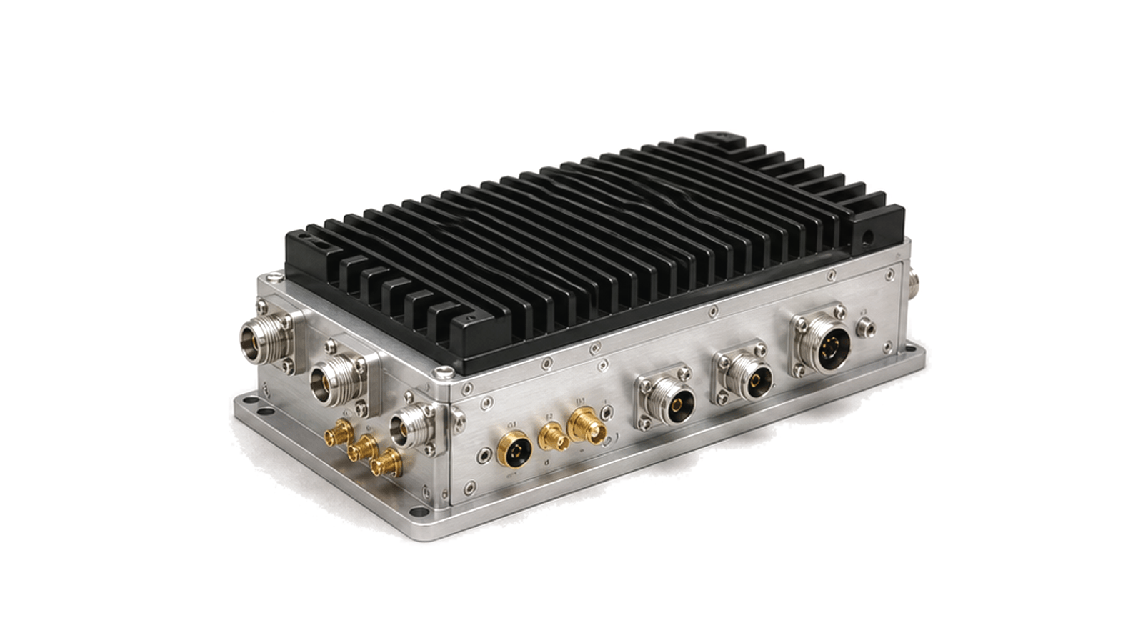
What must be defined before selecting a counter-UAS RF subsystem?
First separate receive-only detection and direction finding from any authorized transmit-mitigation path, then define the signal set, coverage geometry, RF bands, antenna arrangement, co-site environment, control interfaces and measurable acceptance limits for each mode. This family covers RF receive front ends, coherent direction-finding channels, antenna switching or distribution and controlled transmit chains used inside counter-UAS platforms. Complete command systems, radar processors, electro-optical or acoustic sensors and unrestricted interference devices are outside this category.
Separate detection, localization and mitigation
Passive RF detection depends on emissions from the aircraft, controller or link and cannot by itself cover a silent target. State which signals, bandwidths and channel behaviors the receiver must observe; for direction finding, define antenna geometry, channel phase and amplitude tracking, time alignment and calibration. Treat any transmit path as a separate, authorization-dependent function with its own operating bands, permitted modes, duty cycle and inhibit logic.
Protect receiver performance in a crowded RF site
Specify instantaneous and tuning bandwidth, noise figure or input sensitivity at a named reference plane, gain range, selectivity, compression, intermodulation, blocker recovery and maximum safe input. Account for antenna pattern and polarization, feeder loss, preselection, limiter behavior and nearby transmitters. A multi-channel bearing chain also needs matched group delay and repeatable phase across temperature; gain alone does not establish direction-finding performance.
Verify the installed RF boundary
For receive paths, measure gain, noise, dynamic range, channel tracking, image and spurious responses, switching or scan timing and recovery after overload. For authorized transmit paths, verify output level and flatness, modulation or waveform bandwidth, harmonics and out-of-band emissions, antenna mismatch protection, coupling and thermal duty. Repeat critical tests with installed antennas, cables, filters, enclosure, power and co-site emitters represented.
- receive-only, direction-finding and authorized transmit modes
- signals of interest, tuning range, instantaneous bandwidth and channel plan
- receiver noise, gain, selectivity, compression, blockers and safe input
- antenna geometry, polarization, feeder loss, channel phase and calibration
- transmit band, power, duty, spectral limits, mismatch protection and inhibit
- control latency, timestamps, isolation, thermal, environmental and field tests
System and authorization boundary
Approve the RF subsystem only for the documented operating modes and installed reference planes. Detection range, bearing accuracy or mitigation effect belongs to the complete system and scenario; an RF module test alone cannot establish those outcomes, and any transmit operation requires the applicable authorization for the deployment jurisdiction.