
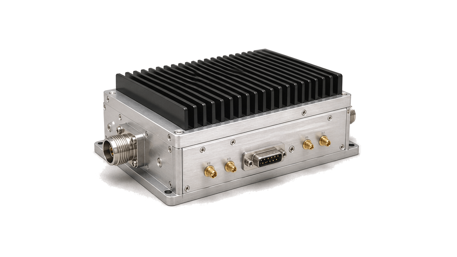
What defines an RF transmitter module rather than a power amplifier?
An RF transmitter module accepts a defined baseband, IF or RF drive and delivers a controlled RF output through an integrated chain that may include conversion, gain, filtering, switching, monitoring, bias and protection. Its specification must therefore describe the waveform and system interfaces as well as output power.
Draw the delivered signal-chain boundary
State the input type and level, required local oscillator or reference, conversion stages, driver and final amplifier, interstage filtering, output switch or isolating device, directional sample, detector, controller and power conversion included in the enclosure. Define connector reference planes, impedance, grounding, supply rails, cooling surface, mechanical interfaces and what remains in the host system. This prevents a power stage and a complete exciter from being compared as equivalent transmitter modules.
Specify useful output under the real waveform
Give operating band, channel bandwidth, modulation, peak-to-average ratio, pulse width, duty cycle and burst pattern. Output power must distinguish CW, average modulated, peak-envelope and saturated ratings. Add gain, gain range, flatness, compression, drain or overall efficiency and output stability. For modulated service, define EVM and adjacent-channel or spectral-regrowth limits at the required delivered power and back-off, rather than relying on a small-signal gain or CW power figure.
Close frequency planning and unwanted-output limits
Identify RF, IF and LO frequencies, sideband sense, tuning step, reference accuracy and settling time. Allocate image rejection, LO leakage, harmonics, nonharmonic spurs, intermodulation, occupied bandwidth and spectrum-mask margin across the module. Filters must be evaluated with frequency tolerance, temperature drift, power and switching states. State whether unwanted-output limits apply at the module connector, after an external filter or at an antenna reference plane.
Make bias, heat and mismatch part of the RF rating
List voltage ranges, quiescent and keyed current, inrush, startup order, gate or drain sequencing, enable logic and fault latching. Convert waveform and duty cycle into dissipated heat at the specified baseplate or ambient condition; include warm-up, thermal foldback and recovery. Define allowable load VSWR by phase, duration and power, and identify circulator, isolator, reflected-power monitor or shutdown behavior. A peak rating without thermal and mismatch conditions is not an operational rating.
Define command and transient behavior
For pulsed, TDD or frequency-agile operation, specify trigger polarity, command latency, RF rise and fall, power droop, overshoot, phase transient, blanking, mute leakage and time to stable frequency and level. State how automatic level control, detector calibration, digital predistortion feedback or external correction interacts with the module. Power-up, inhibit, overtemperature, overcurrent, reflected-power and loss-of-reference states need deterministic outputs and readable status.
Accept the transmitter at calibrated reference planes
Measure gain and S-parameters before compression, then output power, harmonics, spurs, frequency error and noise under representative drive. Use the intended waveform to verify EVM, adjacent-channel power, occupied bandwidth and spectral mask. Repeat at supply and temperature corners, duty-cycle limits and representative mismatches; verify protection and restart. Acceptance records should include drive waveform version, cable and fixture corrections, reference planes, calibration status, firmware, raw traces and pass limits.
RFQ inputs for transmitter modules
- RF band, tuning range and frequency plan
- Input type, level, reference and control interfaces
- Waveform, channel bandwidth and peak-to-average ratio
- CW, average, peak and saturated output definitions
- Gain, flatness, control range and settling
- EVM, adjacent-channel, harmonic and spurious limits
- Duty cycle, pulse or burst timing
- Supply, current, sequencing and fault logic
- Cooling boundary and allowed temperatures
- Load VSWR, reflected power and protection behavior
- Connector planes and acceptance evidence
Category boundary
This category covers integrated RF transmit assemblies that combine two or more functions such as conversion, gain, filtering, switching, monitoring, bias and protection. It excludes standalone power amplifiers, signal generators, antennas and complete radio or radar systems unless those functions are part of the specified delivered transmitter-module boundary.