
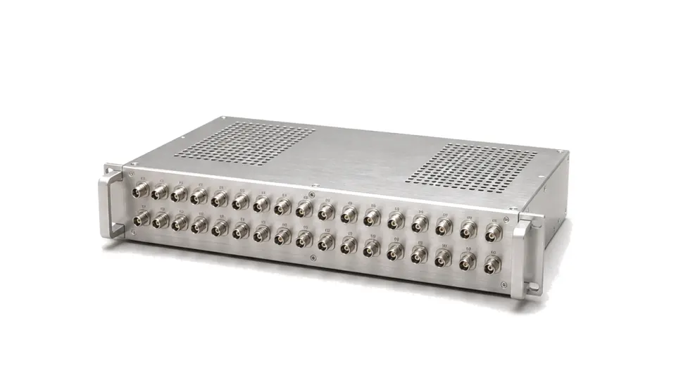
What is an RF test and measurement subsystem?
An RF test and measurement subsystem is the controlled signal-path assembly between test instruments and one or more devices under test. It can combine switching, attenuation or gain, filtering, coupling, detection, limiting, reference distribution and interlocks so an automated bench can apply and measure defined RF states without manual recabling.
Define every test state and reference plane
Start with a route table that identifies stimulus paths, receive paths, loopback states, terminations and prohibited connections. Mark where instrument calibration ends and where subsystem correction begins. A connector count alone cannot show simultaneous-route restrictions, fan-out behavior or whether an inactive port is isolated, open or terminated.
Budget performance for the complete route
Specify insertion loss, return loss or VSWR, isolation, phase, amplitude flatness, noise contribution and compression over frequency for each required state. Include internal cables, adapters and protection elements. The test level at the DUT reference plane, not the source setting, is the value that governs characterization and production limits.
Protect instruments without hiding the measurement
Source power, reflected power, transient energy and switching sequence determine limiter, attenuator and interlock requirements. Protection must recover within the required test cycle and its leakage, settling time and nonlinear behavior must be included in the uncertainty budget. Hot switching and cold switching require separate limits.
Make calibration and maintenance route-specific
Store correction by route, frequency and state; verify path repeatability after switching cycles and temperature changes. Acceptance should include a measured path matrix, calibration method, residual error, state feedback, drift limits and a rule for recalibration or service.
- frequency range, impedance, connectors, channel count and route table
- stimulus, receive, loopback, termination and forbidden states
- path loss, match, isolation, phase, flatness and dynamic range
- CW or pulsed power, reflected power, switching state and protection
- reference planes, correction files, uncertainty and repeatability limits
- control protocol, trigger timing, state readback, interlocks and reports
Approval boundary
Approve the assembled subsystem against the required route matrix and DUT-plane measurement limits. Individual switch or attenuator data cannot replace end-to-end path verification, protection tests and calibration records.