
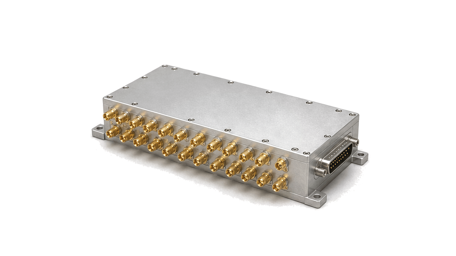
What must an RF beamforming module control in a phased array?
A beamforming module must impose known relative phase or delay and amplitude on every active channel while preserving the RF budget, synchronization and repeatability needed for the array to form a commanded beam. Selection therefore starts with aperture architecture and waveform bandwidth, not with phase range alone.
Set the module boundary at the array interface
Define whether the deliverable is a beamformer core, a transmit or receive tile, a T/R module, a subarray or a complete antenna-facing assembly. Record element count, polarization, RF common and element ports, frequency conversion boundary, power and bias rails, reference clocks, trigger lines, control bus, cooling surface and mechanical datum. The same word 'module' can otherwise hide very different gain, thermal and calibration responsibilities.
Choose phase shift or true time delay from scan bandwidth
Phase shifters reproduce the required inter-element delay at one reference frequency and are efficient for narrow fractional bandwidth. As instantaneous bandwidth and scan angle increase, beam direction varies with frequency and beam squint becomes a system limit. True time delay preserves delay slope across frequency but adds range, resolution, loss, size and control trade-offs. State usable signal bandwidth, scan sector, pointing error and sidelobe requirement before choosing the steering method or hybrid subarray partition.
Close the channel budget in transmit and receive
For every channel, specify gain range and step, phase or delay range and resolution, gain variation versus phase, phase variation versus gain, amplitude and phase balance, return loss, isolation and noise contribution. Transmit paths add output power, compression, efficiency, harmonics, EVM or spectral regrowth and load mismatch. Receive paths add noise figure, input compression, linearity and blocker recovery. Include split or combine loss, T/R switch loss and distribution imbalance in the module result.
Treat beam states as a deterministic timing interface
List the number of stored beam states, command format, addressing, update rate, trigger source, mute behavior and time from command to settled RF output. Arrays with many modules require synchronized loading so channels do not pass through unrelated states. Define power-up state, invalid-command response, fault reporting, telemetry, bias sequencing and whether calibration coefficients live in the module, controller or system configuration store.
Calibrate phase, amplitude and drift at the intended reference plane
Connector, PCB, package, antenna feed, temperature and bias errors all move the realized channel response. A useful calibration plan measures complex gain by channel and frequency, derives phase and amplitude corrections, stores versioned coefficients and verifies them after warm-up and thermal cycling. Conducted calibration can isolate electronics; over-the-air calibration includes the radiating path. Specify which plane the supplied coefficients correct and how replacement modules inherit or regenerate them.
Accept the array by beam performance, not register values
Bench acceptance confirms S-parameters, channel gain, noise, power, phase or delay states, switching time and thermal behavior. Array acceptance then measures beam pointing, scan loss, sidelobes, cross-polarization, EIRP for transmit, G/T for receive and modulation quality where applicable. Test more than boresight: include band edges, representative scan angles, temperature corners and beam-state transitions, with raw data tied to module serial number, firmware and calibration revision.
RFQ inputs for beamforming modules
- Frequency band, signal bandwidth and polarization
- Element and channel count with subarray partition
- Transmit, receive or half-duplex architecture
- Phase-shift or true-time-delay range and resolution
- Gain range, step and channel balance
- Scan sector, pointing and sidelobe limits
- Power, noise figure, linearity and mismatch
- Beam-state count, update and synchronization timing
- Control, telemetry, bias and fault interfaces
- Thermal boundary and calibration reference plane
- Conducted and OTA acceptance data
Category boundary
This category covers multi-channel RF assemblies that control relative amplitude and phase or delay to steer or shape a phased-array beam. It excludes standalone phase shifters, attenuators, beamformer ICs, antennas and complete radar or radio systems unless those items are integrated into the delivered beamforming module boundary.