
LCRF

Privacy preferences

Choose optional purposes independently. You can change or withdraw your choice at any time from the footer.

Strictly necessary

Required for security, session functions and storing your privacy choice.

Always active
Preferences

Remembers optional display or language settings when these features are enabled.

Analytics

Uses first-party visitor and session identifiers to measure pages, referrals and inquiry interactions.

Marketing

Allows marketing measurement or third-party advertising technologies if they are introduced in the future.

Frequency Conversion Subsystems

Frequency conversion subsystems combine converters, mixers, LO references, IF gain, filtering and control in a coordinated RF assembly. They translate signals between operating bands and IF stages for receivers, transmitters and RF test platforms.

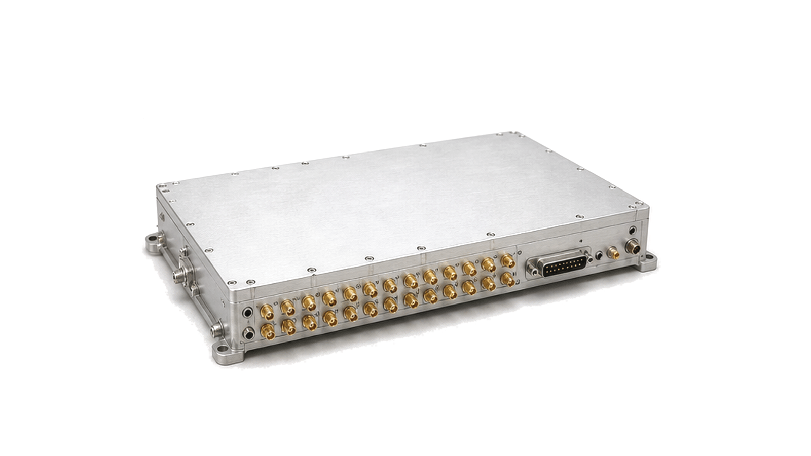
Frequency conversion subsystem with RF connectors and controlled interfaces

FAQ

How do LO drive level and LO leakage affect RF converter performance?

LO drive sets the mixer switching condition and therefore influences conversion response, compression and intermodulation, while LO leakage can disturb antennas, ADCs, amplifiers and adjacent channels.

What is the image response in an RF frequency converter, and how should it be controlled?

An image is an undesired input frequency that produces the same wanted IF through another valid mixing relationship; control it with frequency planning, preselection and verified image or IQ rejection.

Engineering inquiry

Share your RF requirement

Share the product, operating requirements and project context. Our engineering team will route your request to the right specialist.

AttachmentsAttach drawings, BOMs, specifications or test files. Up to 5 files, 10 MB each and 25 MB total.
or drag and dropPDF, DOCX, XLSX, CSV, TXT, JPG, PNG, S1P and S2P
Typically reviewed within one business dayProject information is handled confidentially

Frequency conversion subsystems

Frequency conversion subsystems assemble the frequency-translation portion of an RF or microwave chain into a controlled module. The subsystem may combine upconversion, downconversion, mixing, LO distribution, IF gain, filtering, switching and monitoring in one mechanical and electrical boundary.

RF, LO and IF planning

Important data includes input and output frequency ranges, IF plan, LO or reference requirements, conversion gain or loss, gain flatness, image rejection, spurious products, phase-noise contribution, bandwidth, isolation, control interface, supply requirements and connector format. These values determine where the signal is placed, how cleanly it is translated and how easily the subsystem can be integrated into receivers, transmitters, radar channels, spectrum equipment and automated RF test platforms.