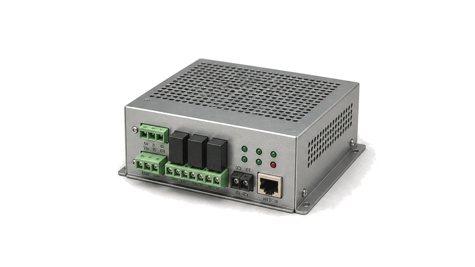
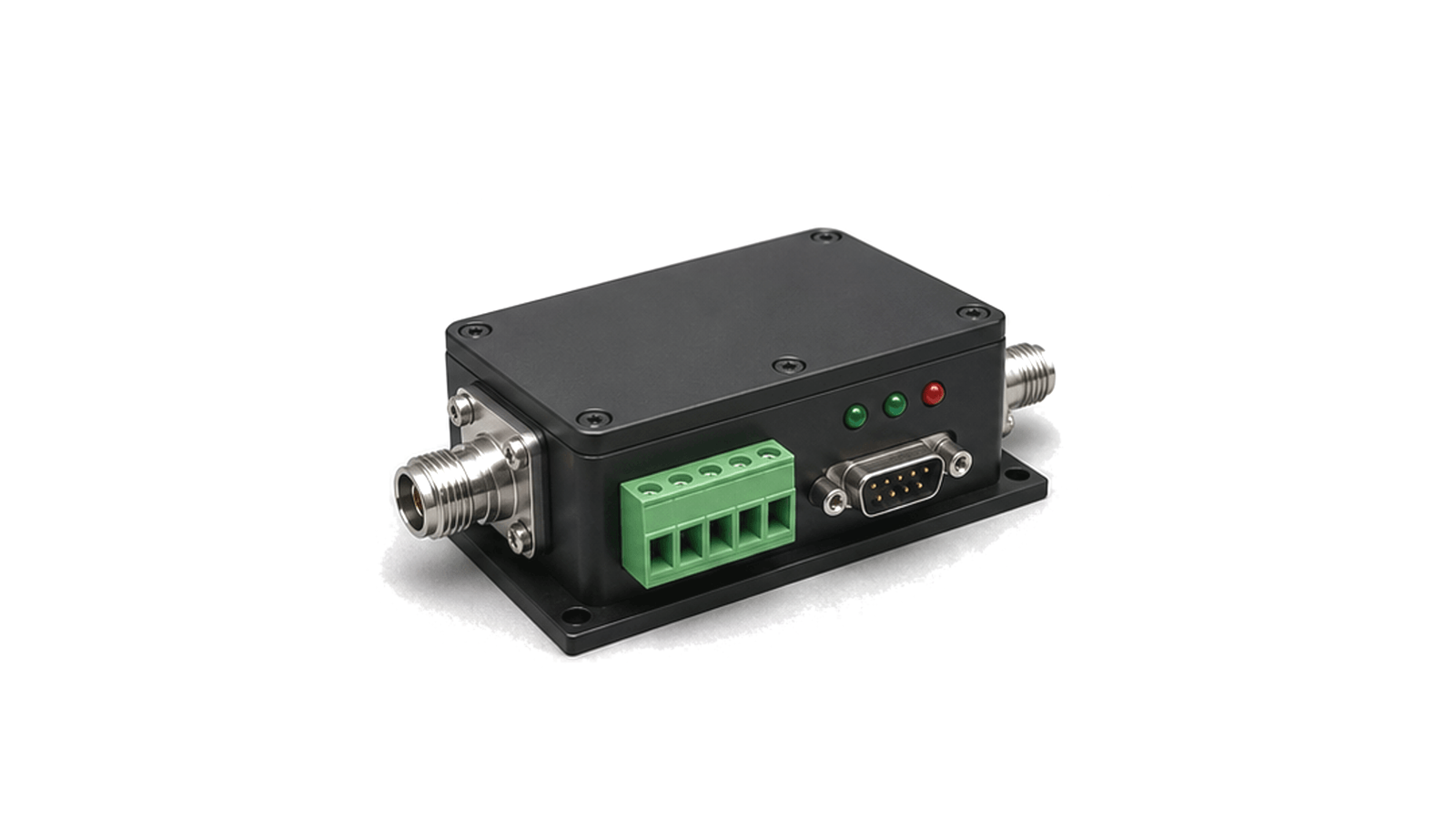
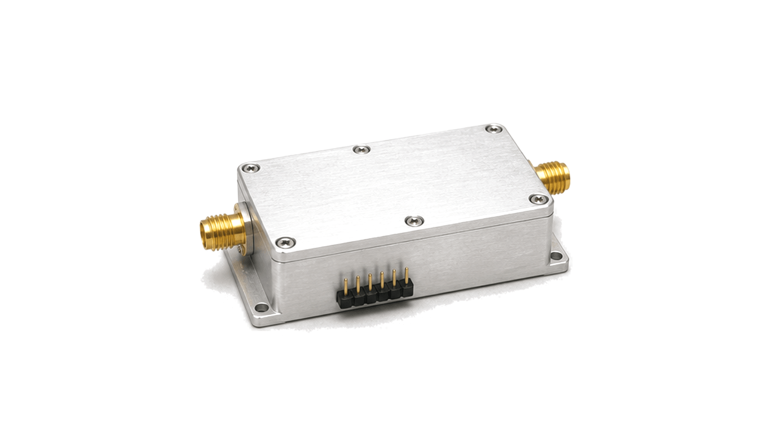
Bias Control and Protection
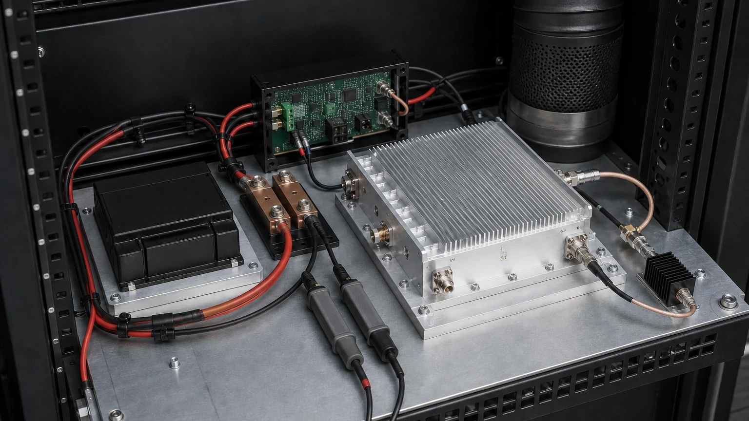
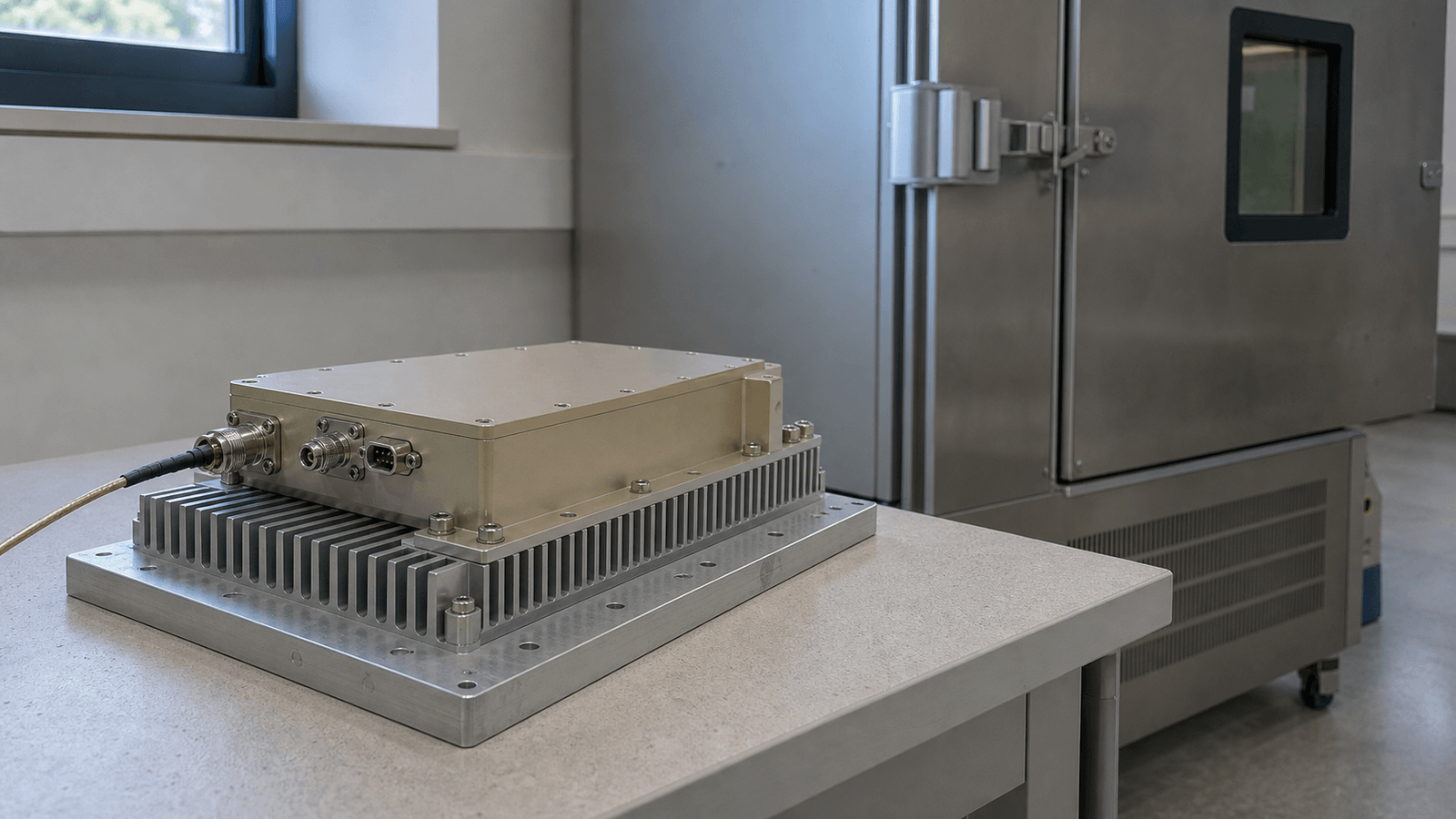
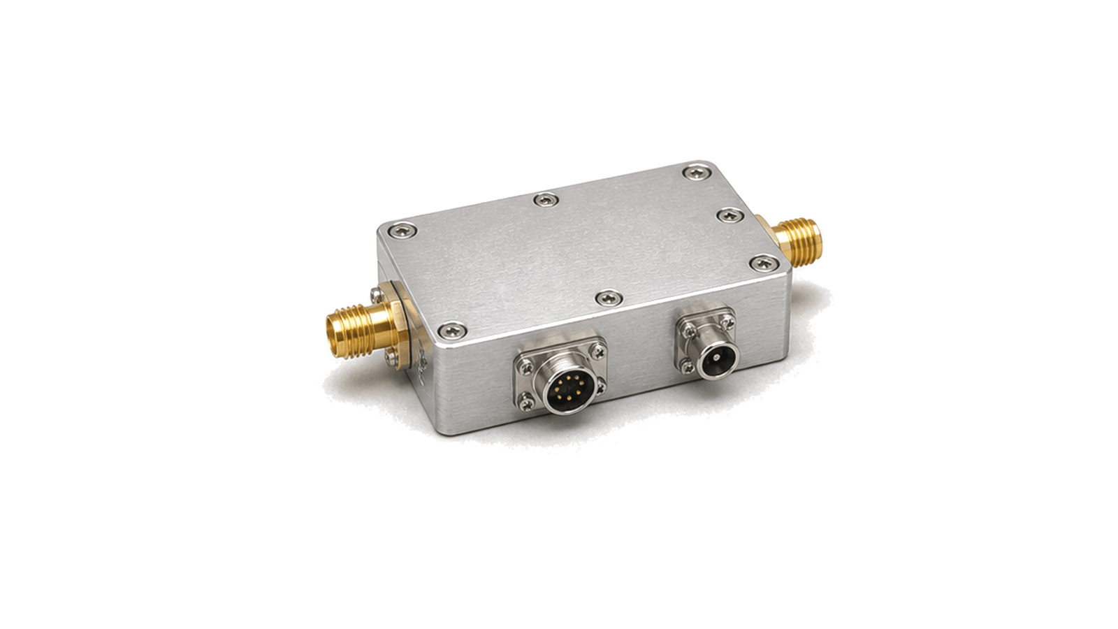
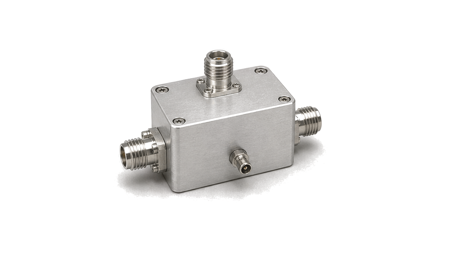
Bias control and protection hardware provides controlled voltage and current paths for active RF devices, amplifier stages and front-end modules. It keeps the RF path inside its electrical and thermal limits while monitoring conditions that can damage devices or change operating behavior.
Control boundary
The boundary includes voltage rails, enable logic, startup and shutdown order, current sensing, temperature sensing, reflected-power or fault input handling and protection response. The circuit around the RF device is as important as the RF path because incorrect bias or delayed protection can shorten lifetime or change output stability.
Engineering data
Useful records include rail voltage, current limit, enable sequence, soft-start timing, monitor interface, trip threshold, reset behavior, thermal sensor position and safe-state logic.
Define one electrical-and-thermal operating envelope
- Bias Control and Protection architecture
- Keep the article boundary on support hardware
- Bias Control and Protection design requirements
- Freeze operating states before choosing hardware
- Bias Control and Protection integration
- Specify voltage at the module terminals, not only at the source
- Bias Control and Protection test and verification
- Size current from the driven profile and fault envelope
How to Specify Power, Bias, Protection and Thermal Interfaces for an RF Power Module
An engineering workflow for turning RF operating modes into DC rail, current transient, ripple, sequencing, protection, heat-load, cooling-interface and acceptance requirements without confusing catalog ratings with delivered system performance.