
LCRF

Privacy preferences

Choose optional purposes independently. You can change or withdraw your choice at any time from the footer.

Strictly necessary

Required for security, session functions and storing your privacy choice.

Always active
Preferences

Remembers optional display or language settings when these features are enabled.

Analytics

Uses first-party visitor and session identifiers to measure pages, referrals and inquiry interactions.

Marketing

Allows marketing measurement or third-party advertising technologies if they are introduced in the future.

Variable Attenuators

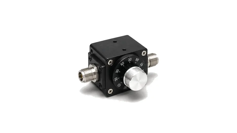
Variable attenuators change RF signal level across an adjustable range. They are used in lab alignment, receiver sensitivity checks, level sweeping, gain balancing and RF paths that need repeatable but non-fixed loss.

Variable RF attenuator for adjustable signal level control

Articles

FAQ

How often should an RF test path be verified with a check standard or recalibrated?

Use both time-based intervals and event triggers, with an independent check standard that can reveal drift, cable or connector damage, switch-state change and fixture instability between full calibrations.

Why must a passive RF impedance network have a defined reference plane and complex S-parameters?

The reference plane determines where impedance and waves are defined; complex S-parameters retain magnitude and phase needed to move planes, de-embed fixtures and predict network interaction.

What is an RF measurement reference plane, and when is fixture de-embedding required?

The measurement reference plane is the electrical boundary where a corrected value is claimed; de-embedding is needed only when a characterized fixture network must be removed to report at a different DUT plane.

Engineering inquiry

Share your RF requirement

Share the product, operating requirements and project context. Our engineering team will route your request to the right specialist.

AttachmentsAttach drawings, BOMs, specifications or test files. Up to 5 files, 10 MB each and 25 MB total.
or drag and dropPDF, DOCX, XLSX, CSV, TXT, JPG, PNG, S1P and S2P
Typically reviewed within one business dayProject information is handled confidentially

Variable attenuators

Variable attenuators provide adjustable loss in an RF path. They are useful when a signal level must be trimmed during setup, swept during testing or changed by an analog or mechanical control rather than fixed at one value.

Adjustment range and repeatability

Key data includes attenuation range, control method, resolution or setting scale, repeatability, insertion loss, frequency flatness, VSWR, power rating, connector type and mechanical format. These details matter in lab alignment, receiver sensitivity work, gain balancing and signal-level margin checks.

What does the Variable Attenuators category cover?

Variable attenuators change RF signal level across an adjustable range. They are used in lab alignment, receiver sensitivity checks, level sweeping, gain balancing and RF paths that need repeatable but non-fixed loss.

How should hardware in the Variable Attenuators category be selected?

A practical method for specifying passive RF loads, terminations and impedance networks by function, reference plane, complex impedance, reflection, insertion loss, waveform power, thermal derating, environment and acceptance evidence.

  • Define the electrical and thermal boundary before choosing the hardware
  • Classify the passive function before selecting a component
  • Freeze frequency, characteristic impedance and the reference plane

Which specifications matter when evaluating Variable Attenuators?

Key data includes attenuation range, control method, resolution or setting scale, repeatability, insertion loss, frequency flatness, VSWR, power rating, connector type and mechanical format. These details matter in lab alignment, receiver sensitivity work, gain balancing and signal-level margin checks.

How should hardware in the Variable Attenuators category be tested and verified?

Specify a passive RF network or load by first naming its function and calibrated reference plane. Freeze continuous frequency coverage, characteristic impedance, port state, return loss or VSWR, insertion response, average and peak power, pulse width, duty cycle, mismatch or reverse power, mounting temperature, cooling, connector and environment. Then define VNA calibration, power-stress conditions, thermal stabilization, pass/fail limits and retained data.

How to Specify Passive RF Networks and Loads: Impedance, Return Loss, Power, Bandwidth and Thermal Limits