
LCRF

Privacy preferences

Choose optional purposes independently. You can change or withdraw your choice at any time from the footer.

Strictly necessary

Required for security, session functions and storing your privacy choice.

Always active
Preferences

Remembers optional display or language settings when these features are enabled.

Analytics

Uses first-party visitor and session identifiers to measure pages, referrals and inquiry interactions.

Marketing

Allows marketing measurement or third-party advertising technologies if they are introduced in the future.

Power Control Units

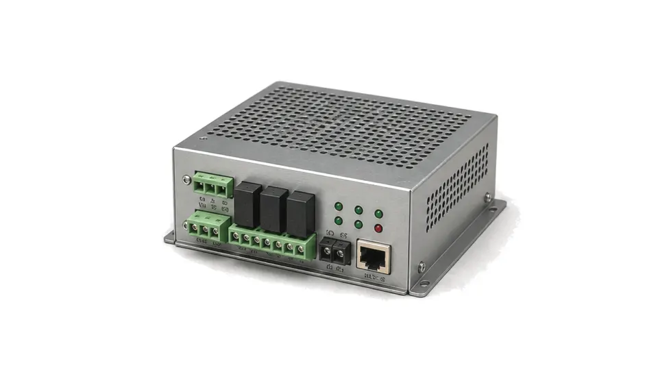
Measurement feedback depends on detector response. Power Control Units sits within Power, Bias & Thermal Support and supports RF modules with stable power, bias, cooling or protection hardware. The content focuses on voltage range, current rating, thermal resistance, monitoring signals and protection thresholds for engineers, sourcing teams and system integrators.

Power Control Units

FAQ

What bias sequencing and protection are required for an RF power amplifier?

Use the approved module or device sequence, with explicit thresholds, timing, current windows, RF-enable interlock, fault action and controlled power-down.

How should an RF power amplifier supply be sized for peak current, duty cycle and load transients?

Separate average and RMS heating from pulse-on current, edge-rate demand, inrush and fault current, then verify rail droop and recovery at the module terminals.

Engineering inquiry

Share your RF requirement

Share the product, operating requirements and project context. Our engineering team will route your request to the right specialist.

AttachmentsAttach drawings, BOMs, specifications or test files. Up to 5 files, 10 MB each and 25 MB total.
or drag and dropPDF, DOCX, XLSX, CSV, TXT, JPG, PNG, S1P and S2P
Typically reviewed within one business dayProject information is handled confidentially

Power Control Units

Measurement feedback depends on detector response. Power Control Units supports RF modules with stable power, bias, cooling or protection hardware for power amplifiers, remote RF assemblies, laboratory racks and rugged subsystems. The information is organized around how this hardware is used in an RF system.

Key data centers on voltage range, current rating, thermal resistance, monitoring signals and protection thresholds. Those details help engineering, sourcing and integration teams compare the record against the actual signal path, mechanical boundary and operating environment.

When reviewed with model data, outline dimensions, test conditions and delivery documents, the content makes project scope, constraints and follow-up verification points easier to align early.