
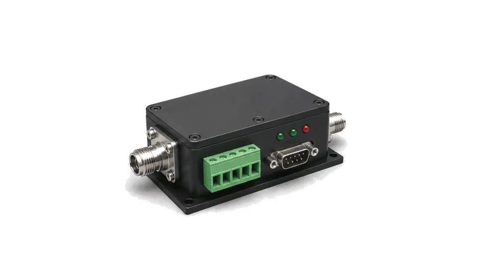
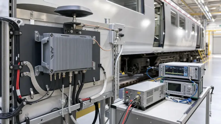
What should a power protection and monitoring module protect?
It should keep the protected load and upstream supply within safe voltage, current, energy, sequence and temperature limits while reporting enough state to diagnose and recover from a fault. This family covers DC power-path supervision for RF and microwave assemblies. RF input limiters, coaxial surge protectors and bias tees remain in their signal-path categories.
Define source, load and fault envelopes
Record nominal and absolute rail limits, steady and pulsed current, startup capacitance, allowable droop, hold-up energy, reverse current, source impedance and grounding. Convert likely faults—brownout, overvoltage, reverse polarity, short circuit, overload, backfeed and repeated power cycling—into threshold, delay and energy requirements.
Choose protection behavior, not just a current rating
Specify inrush control, undervoltage and overvoltage action, current limit or foldback, short-circuit response, reverse blocking, thermal shutdown and sequencing. Decide whether faults latch, retry, isolate or degrade safely. Threshold accuracy, hysteresis, blanking time, response time and safe-operating area determine whether nuisance trips or destructive energy dominate.
Make monitoring useful for control and acceptance
Define voltage, current and temperature accuracy, bandwidth, sampling, alarms, power-good logic, telemetry interface, event history and fault reset. Validate startup, load steps and every credible fault at temperature and supply extremes. Measure both load protection and stress transferred to connectors, switches, wiring and the upstream source.
- input and output voltage ranges and absolute limits
- continuous, pulse, startup and short-circuit current
- inrush, sequencing, hold-up and reverse-energy paths
- threshold accuracy, hysteresis, delay, response and retry policy
- voltage, current, temperature, alarms and telemetry
- thermal design, fault energy, coordination and recovery tests
Acceptance boundary
Approve the module with the real source impedance, wiring, load capacitance, operating sequence and fault energy represented. A trip threshold measured at room temperature does not prove safe interruption, discrimination, telemetry or recovery in the installed system.