
How should an RF switching and routing architecture be selected?
Select the architecture only after the valid route map, simultaneous connections, frequency range, power in every state, allowable path loss and isolation, switching sequence, control interface, service life and calibration plane are defined. A fast switch with attractive headline isolation can still fail if an inactive path leaks, a live source is switched into an open load, or the controller permits an illegal route.
Start with the route map and delivered boundary
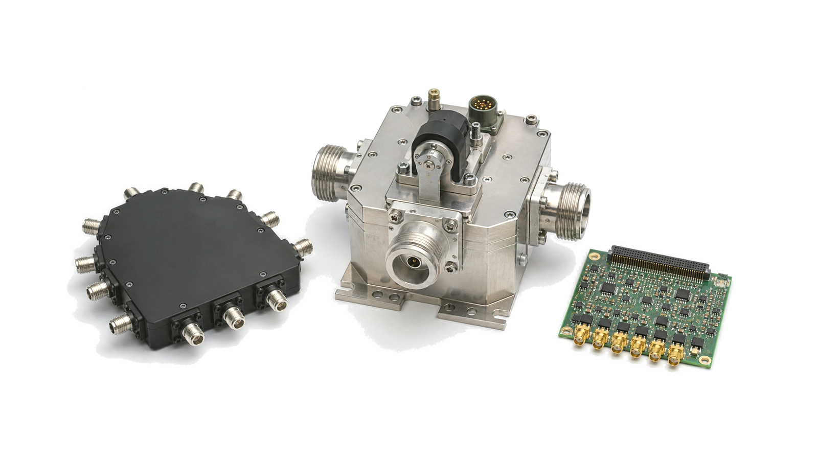
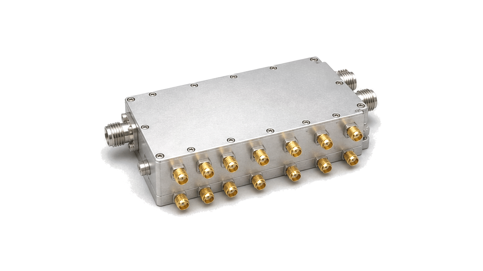
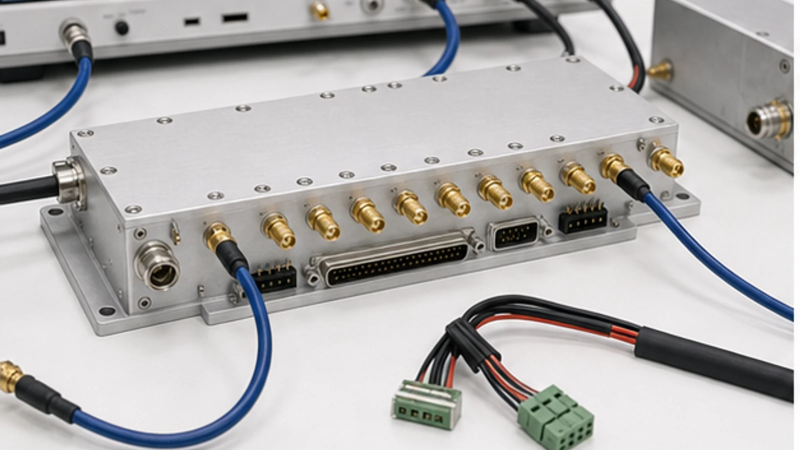
List every source, destination, bidirectional port, termination and route that must or must not exist. State whether the delivered item is a semiconductor switch, coaxial or waveguide switch, electromechanical relay, T/R switch, matrix, control board or a combined assembly. Define simultaneous paths, broadcast or fan-in states, connector reference planes, fail-safe position and whether unused ports are internally terminated. This topology prevents an SPnT data sheet from being mistaken for a complete routing system.
Budget RF performance for every active and inactive path
Create a path table over frequency, temperature and switch state. Record insertion loss and flatness, input and output return loss, isolation to each inactive port, path-to-path crosstalk, amplitude and phase repeatability, leakage during transition and the cumulative loss through cascaded stages. Isolation measured between adjacent ports under one termination condition may not predict a populated matrix. Include cable, connector, relay and board losses at the same reference planes used for system acceptance.
Rate power, linearity and mismatch under the actual switching event
Specify CW, pulsed or modulated power, duty cycle, crest factor, compression and intermodulation limits. Distinguish cold switching from switching while RF is present; permissible live-switch power can be far below steady-state power. Define source and load mismatch, DC bias, transient energy, hot-spot temperature and survivability by phase if reflected power is significant. For receive paths, add noise contribution, leakage desensitization and protection recovery instead of relying only on maximum input power.
Make control sequencing and safe states part of the RF requirement
Document logic levels, control polarity, command protocol, address scheme, status readback, switching latency and settling time at the RF output. Define break-before-make or make-before-break behavior, source mute timing, amplifier bias sequencing, interlocks, route conflict rules and the state after reset, watchdog timeout or power loss. A controller should reject unsafe combinations and report the route actually achieved, not merely acknowledge that a command was received.
Plan repeatability, lifetime, calibration and maintenance
Semiconductor switches trade switching speed and cycle life against linearity, loss and power; electromechanical devices trade slower operation and finite mechanical life for low loss and high isolation. State rated operations under load, contact monitoring, drift limits and replacement access. For measurement systems, define path-specific correction data, calibration interval, reference standards, serial-number traceability and what happens after a relay, cable or module is replaced. Calibration cannot compensate for unstable routes or unmeasured leakage.
Verify the complete route matrix under representative loads
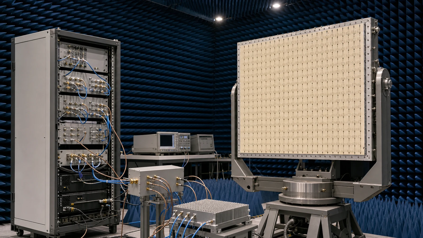
Test every permitted route and a justified set of forbidden-state pairs, not only one nominal path. Measure loss, match, isolation, crosstalk, compression, intermodulation, switching transient, latency, settling and repeatability with realistic sources, loads and simultaneous activity. Cycle high-use routes, exercise reset and fault states, repeat at power and temperature limits, and retain the route table, firmware version, calibration files, instrument settings, cable corrections and pass limits as acceptance evidence.
RFQ inputs for switching, routing and control
- Source, destination and bidirectional port map
- Permitted, forbidden and simultaneous routes
- Frequency range and connector reference planes
- Path loss, flatness, return loss and isolation limits
- Crosstalk and leakage in inactive and transition states
- CW, pulsed or modulated power and live-switch condition
- Compression, intermodulation, mismatch and bias conditions
- Switching time, RF settling and route repeatability
- Control protocol, logic, readback and interlocks
- Fail-safe, reset, watchdog and power-loss state
- Operation count, environment and maintenance boundary
- Calibration method and full-matrix acceptance evidence
Category boundary
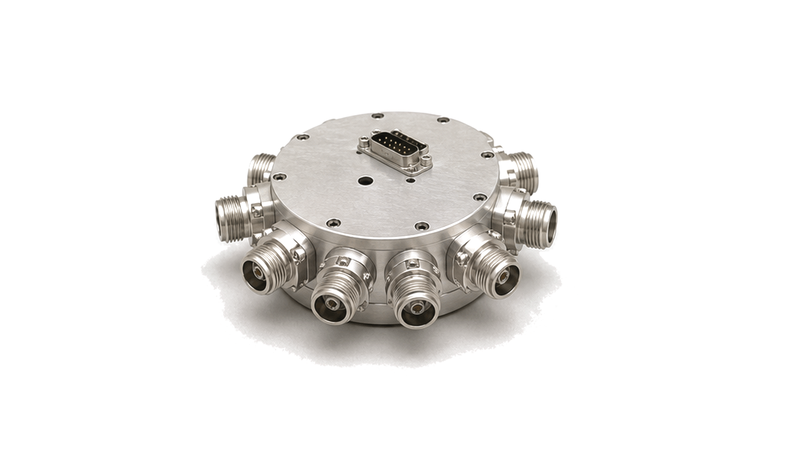
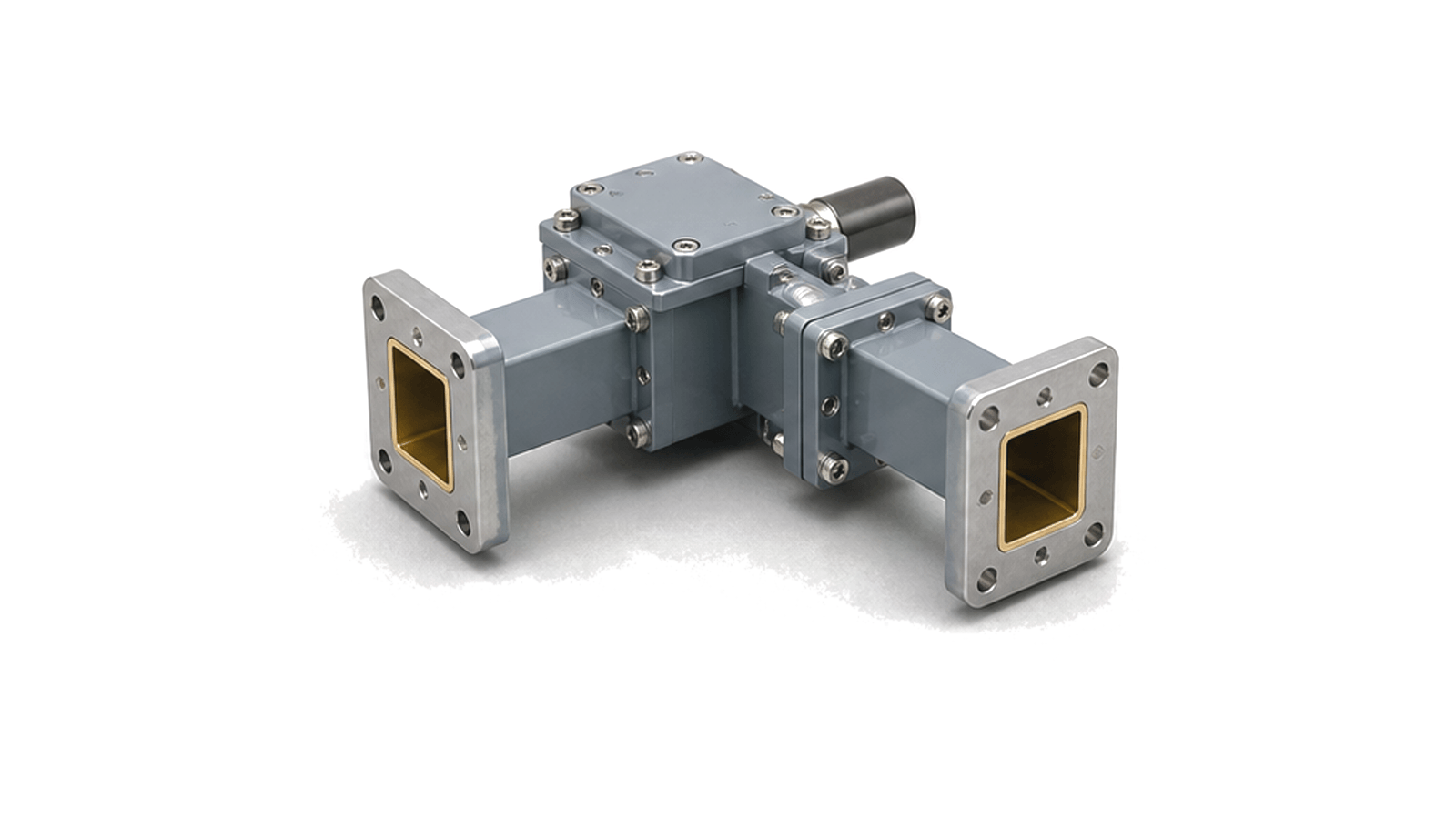
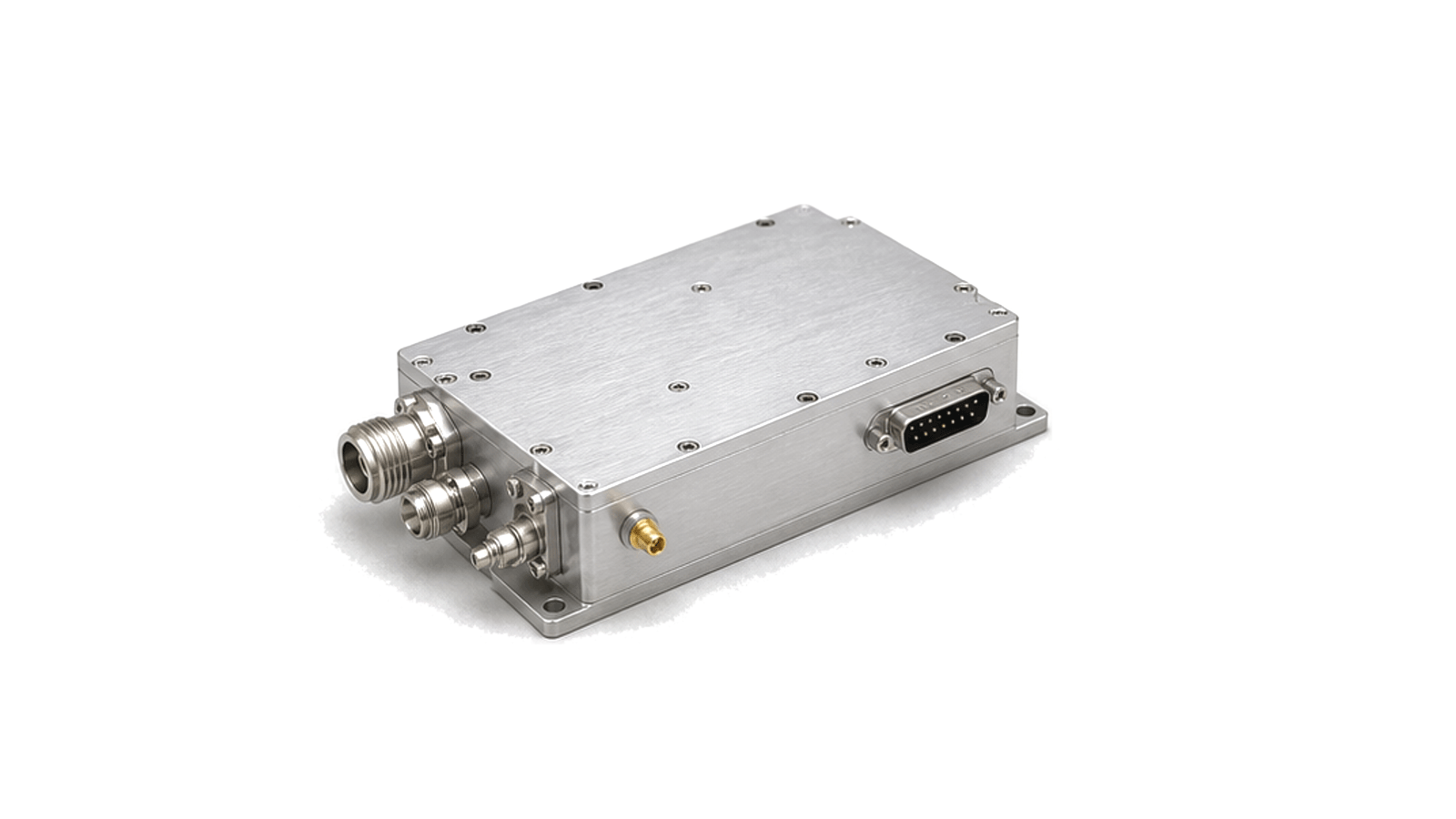
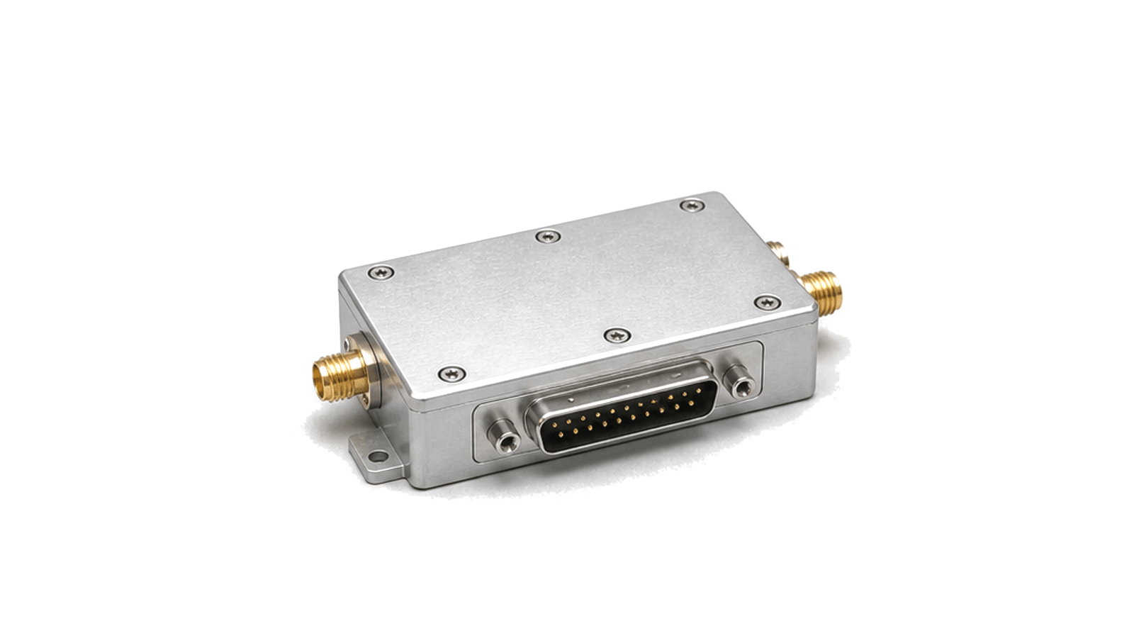
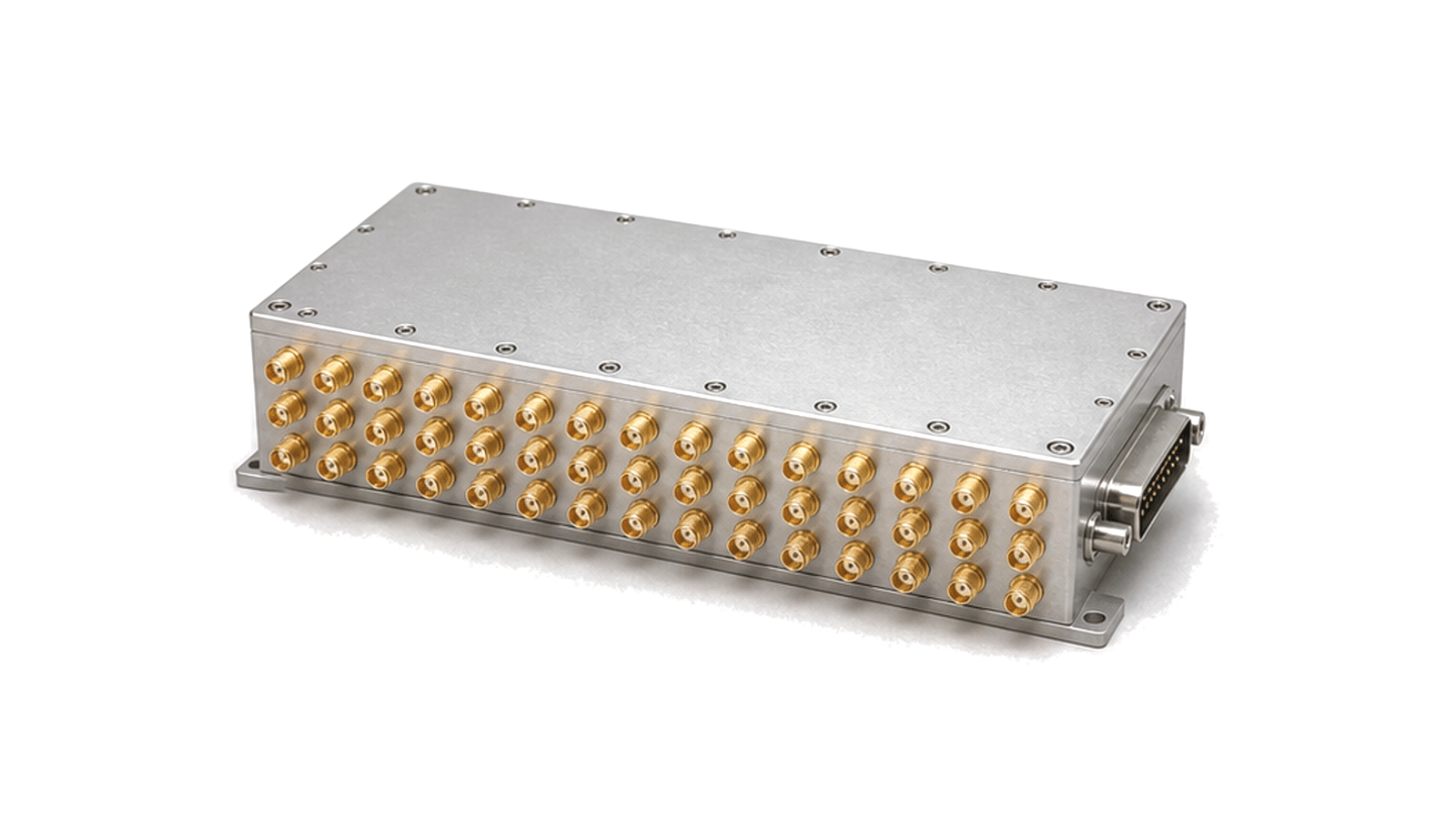
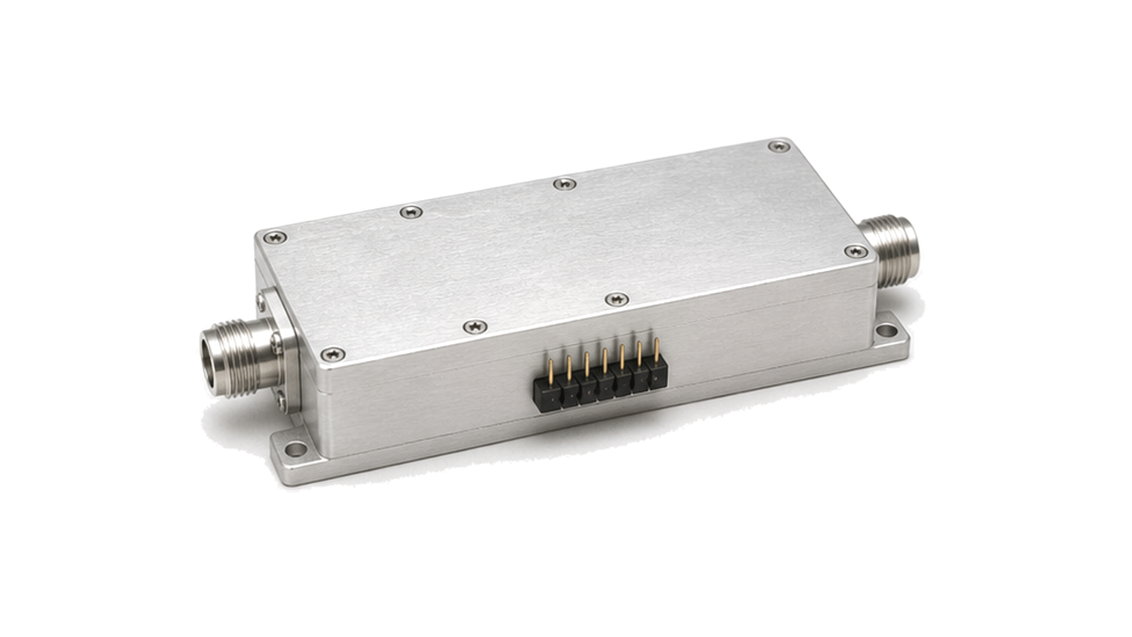
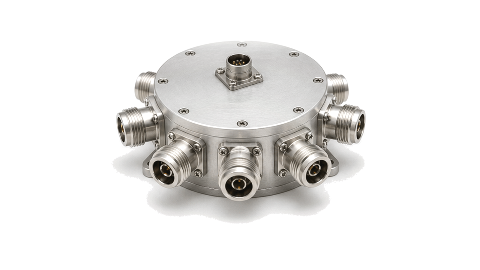
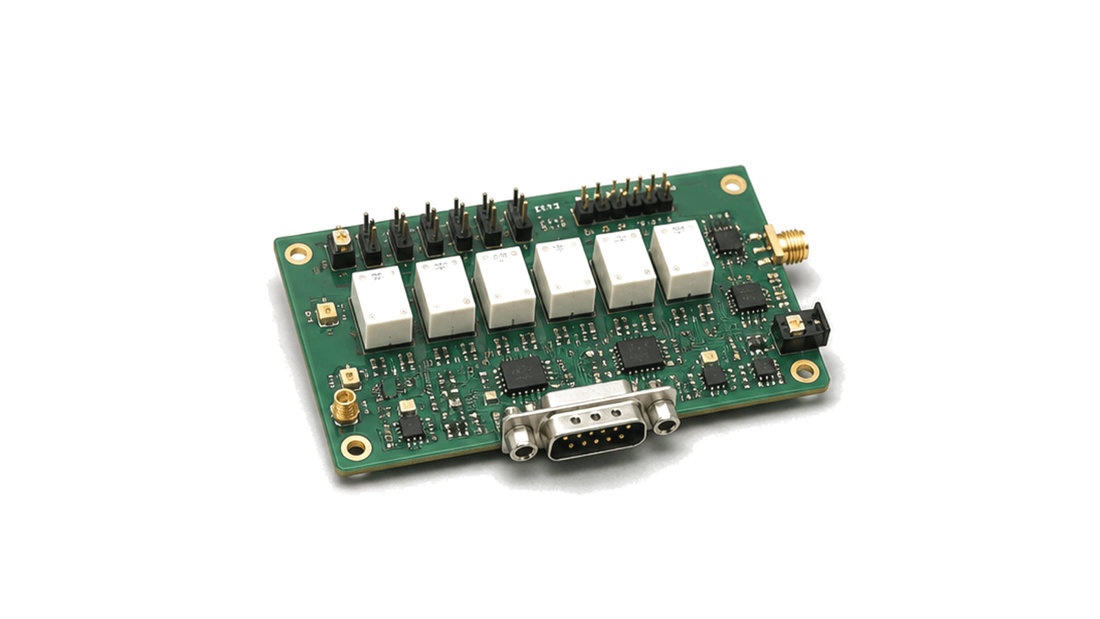
This parent category covers RF and microwave switching, routing and control hardware that selects, connects, disconnects or terminates signal paths, including semiconductor, coaxial, electromechanical and waveguide switches, relays, T/R switches, matrices and integrated route controllers. It does not replace the dedicated child pages for a specific switch technology, and excludes fixed passive networks, standalone attenuators or phase shifters, general digital controllers without an RF path, and complete test racks or receiver chains except where linked as system contexts.
Start with a route-state contract, not a switch technology
- Switching, Routing & Control supplier / Switching, Routing & Control manufacturer
- Freeze topology and port states before selecting hardware Begin with a state table. An SPST opens or closes one path; an SPDT selects between two paths; an SPnT selects one of several throws; a transfer switch exchanges two paired paths; and a matrix may be blocking, nonblocking or partially fan-out capable. These labels are not interchangeable....
- Switching, Routing & Control technical specifications
- Budget loss, match, isolation and crosstalk over the complete route Specify a continuous operating range at named connector planes. The narrowest switch, connector, cable, transition and termination defines the usable path. Add the maximum insertion loss of every series element, then include cable aging, temperature drift and connector repeatability....
- Switching, Routing & Control selection guide
- Freeze topology and port states before selecting hardware Begin with a state table. An SPST opens or closes one path; an SPDT selects between two paths; an SPnT selects one of several throws; a transfer switch exchanges two paired paths; and a matrix may be blocking, nonblocking or partially fan-out capable. These labels are not interchangeable....
- Switching, Routing & Control test and verification
- Verify every required route and every dangerous transition
How to Select an RF Switch or Switch Matrix: Topology, Loss, Isolation, Power and Control
A practical method for turning route states, frequency coverage, leakage limits, waveform power, switching sequence and control interfaces into an RF switch or matrix specification that can be verified path by path.