
LCRF

Privacy preferences

Choose optional purposes independently. You can change or withdraw your choice at any time from the footer.

Strictly necessary

Required for security, session functions and storing your privacy choice.

Always active
Preferences

Remembers optional display or language settings when these features are enabled.

Analytics

Uses first-party visitor and session identifiers to measure pages, referrals and inquiry interactions.

Marketing

Allows marketing measurement or third-party advertising technologies if they are introduced in the future.

Band-stop / Notch Filters

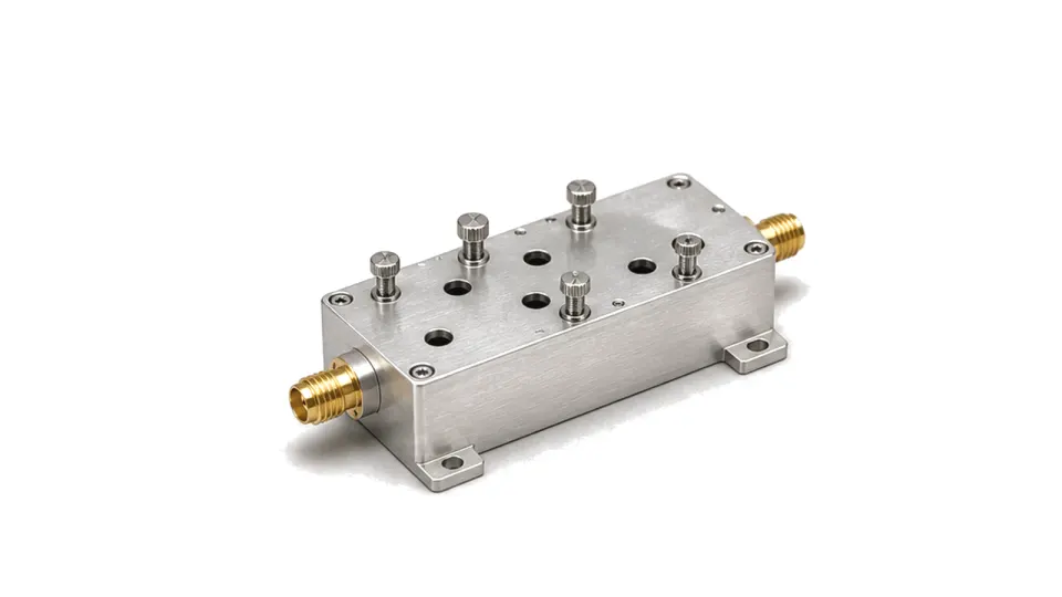
Band-stop and notch filters reduce a defined interference band while allowing nearby useful RF or microwave spectrum to remain in the path. They are used for spur rejection, coexistence filtering, receiver protection and test setups with known unwanted tones.

Band-stop RF notch filter with coaxial connectors

FAQ

What is the difference between RF filter insertion loss and return loss?

Insertion loss measures transmission reduction through the intended path; return loss measures mismatch at a port under defined terminations, so both are needed.

How should RF filter power handling be derated for insertion loss and temperature?

Derate RF filter power from actual dissipated heat, mismatch and field stress at the declared CW or pulsed waveform, mounting and temperature, then recheck the frequency mask at equilibrium.

Engineering inquiry

Share your RF requirement

Share the product, operating requirements and project context. Our engineering team will route your request to the right specialist.

AttachmentsAttach drawings, BOMs, specifications or test files. Up to 5 files, 10 MB each and 25 MB total.
or drag and dropPDF, DOCX, XLSX, CSV, TXT, JPG, PNG, S1P and S2P
Typically reviewed within one business dayProject information is handled confidentially

Band-stop and notch filters

Band-stop and notch filters are used when a system must suppress a known frequency or narrow interference region without removing the wider operating band around it. The filter creates a rejection window inside the signal path instead of passing only one selected band.

Interference rejection inside a wider path

Important data includes notch center frequency, rejection depth, notch bandwidth, passband insertion loss, return loss, Q factor, power handling, connector type, package size and temperature stability. These values matter in coexistence paths, receiver front ends, telemetry channels, radar test benches and RF measurement systems where one unwanted component must be reduced without redesigning the full channel.