
What does an RF triplexer do?
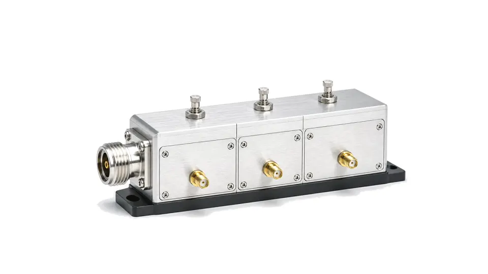
An RF triplexer is a reciprocal frequency-selective network with one common port and three band ports. It combines three non-overlapping RF bands onto a shared feeder or separates a composite signal into the correct branches while maintaining match and isolation.
Freeze the four-port frequency plan first
State the common port, each branch-port label, three passbands, guard bands, transition regions and every stopband before comparing hardware. A triplexer is usable only when the complete allocation fits the radio plan; three attractive center frequencies do not define the required crossover behavior or adjacent-band rejection.
Compare path and cross-path specifications
Review insertion loss and ripple from the common port to each branch, return loss at all four ports, and isolation for every branch-port pair across both passbands and stopbands. Add absolute group delay or delay variation when modulation bandwidth, timing alignment or phase consistency matters. Power must be stated per branch and at the common port, including average, peak, duty cycle and simultaneous-carrier conditions.
Separate a triplexer from neighboring passive networks
A duplexer or diplexer separates two frequency regions; a triplexer separates three. A three-way splitter divides broadband power and normally does not provide frequency-selective routing. A combiner may refer to several architectures, so the RFQ must say whether the required unit is a reciprocal triplexer, a directional combining network or a switched filter bank.
Account for passive nonlinearity and service conductors
In high-power multicarrier infrastructure, passive intermodulation can dominate even when small-signal loss and isolation pass. Specify carrier count, carrier power, test frequencies, order, measurement units and limit. Declare whether direct current, remote-control signalling or surge energy must pass through selected branches; an undocumented bypass path changes both filtering and protection behavior.
Validate the complete multiport device
Use a calibrated four-port network-analyzer setup, or a controlled reconnection plan, with reference planes at the production connectors. Terminate every unmeasured port in the specified impedance. Record the full scattering-parameter matrix, not only the three forward paths, and verify edge frequencies, temperature, power and passive-intermodulation conditions against one acceptance table.
RFQ data that prevents a false match
- Common-port and branch-port diagram with labels
- Three passbands, transition bands and rejection masks
- Insertion loss, ripple and return loss for every path
- Pairwise branch isolation over all relevant bands
- Average and peak power with carrier and duty conditions
- Passive-intermodulation method and limit where applicable
- Direct-current, control-signal and surge-bypass requirements
- Connector, mounting, ingress and temperature requirements
- Touchstone data and production acceptance report
Category boundary
This category covers passive frequency-selective triplexers that combine or separate three RF bands through a common port. It excludes broadband three-way power dividers, two-band duplexers or diplexers, switched filter banks, active channelizers, transceivers, antennas and complete base-station systems unless those functions are explicitly integrated and documented.