
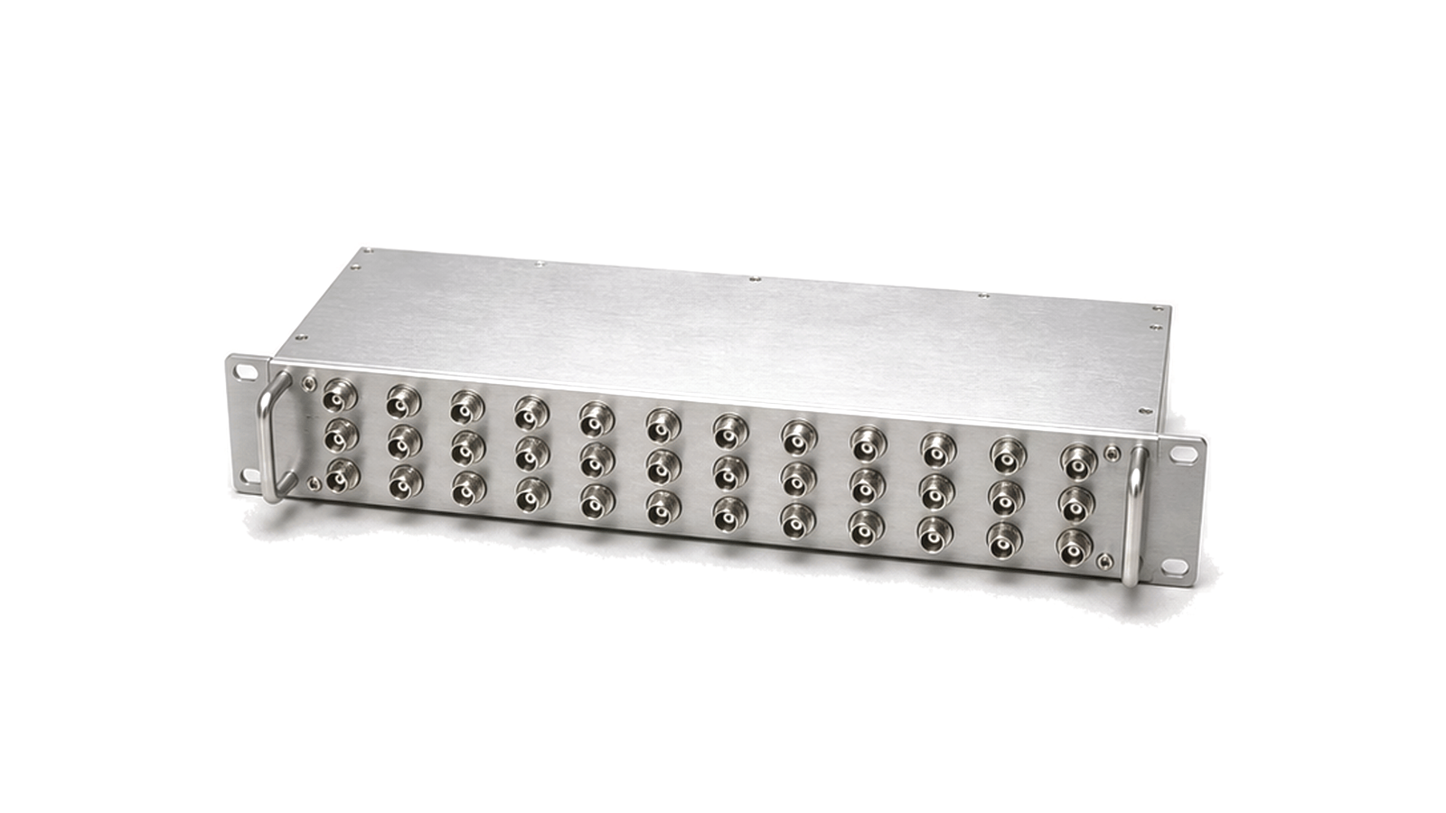
What should be specified for an RF distribution unit?
Specify the source and signal type, frequency band, impedance, input range, number of independently buffered outputs, output level, path-to-path amplitude and phase limits, additive noise, isolation, linearity, redundancy, monitoring and acceptance test conditions. An RF distribution unit accepts one selected RF, local-oscillator or frequency-reference input and reproduces it at several isolated outputs. Active buffering can recover splitter loss and stop one connected load from disturbing the others, but the unit then contributes gain error, noise, distortion, delay and failure modes that a passive divider does not. A block diagram must show whether every output is continuously active, individually enabled, switched between A and B sources, or available only as a cascade port.
Define the source, fan-out and coherence requirement
Start with the actual waveform and source contract: carrier or reference frequency, modulation or pulse content, source impedance, nominal and fault input levels, allowed source loading and whether phase coherence is required. Record the number of simultaneously usable outputs, connector and impedance at every port, cable-reference planes and whether unused outputs must be terminated. For coherent LO, radar or multi-channel test distribution, specify channel-to-channel phase spread, amplitude tracking, group-delay or time skew and temperature drift rather than relying on a single nominal gain figure.
Balance gain, noise, isolation and linearity
Frequency coverage and gain flatness set only the first boundary. Compare output-level accuracy, gain or attenuation range, input and output return loss, reverse and output-to-output isolation, additive phase noise, residual spurious products, harmonic distortion, noise figure or output noise floor, compression and intermodulation margin. Confirm whether headline isolation assumes every port is matched and whether a disabled or faulted output remains isolated. The worst credible input level, simultaneous output loading and cascade depth must remain below compression while the weakest source still meets downstream sensitivity and phase-noise limits.
Treat monitoring and redundancy as part of the RF path
For primary and backup inputs, define what triggers a transfer, the switching threshold, qualification time, failover duration, phase or amplitude discontinuity and alarm behavior. Output-level telemetry, source-frequency checks, remote enable, event logs and network control are useful only when their accuracy, update rate, startup state and loss-of-communications behavior are stated. Redundant AC or DC feeds do not prove RF continuity; source switching, amplifier bypass, thermal recovery and power-cycle behavior require separate acceptance limits.
Verify every path at the installed reference planes
Measure gain, flatness, return loss and isolation for every input-output combination with all other ports in their specified loads. Use a phase-noise or residual-noise method that separates the source from the distribution unit, and compare channel phase and delay with equalized cables or fixture removal. Repeat critical measurements at minimum and maximum input, full output loading, temperature and supply extremes. Exercise output enables, A/B transfer, alarms, remote control and recovery after power interruption while observing RF transients. Reject a unit whose data covers only a typical path, hides additive noise, or leaves failover and unmatched-port behavior undefined.
- Signal type, frequency range, impedance, connectors and input-level window
- Input count, output count, cascade ports, enables and source-selection logic
- Gain, flatness, output accuracy, return loss and full-load linearity
- Additive phase noise, spurious response, channel amplitude, phase and delay tracking
- Output-to-output and reverse isolation under matched, disabled and faulted states
- Monitoring accuracy, alarms, failover transient, power recovery and environmental limits
Category boundary
This category covers active or buffered RF signal distribution modules and rack units that reproduce one selected RF or reference source at multiple isolated outputs, with optional gain control, monitoring and redundant-source switching. Passive power dividers and combiners, directional couplers, RF switch matrices, DC power distribution units and digital-only clock fan-out devices follow different loss, routing, protection or logic rules and are selected separately.