
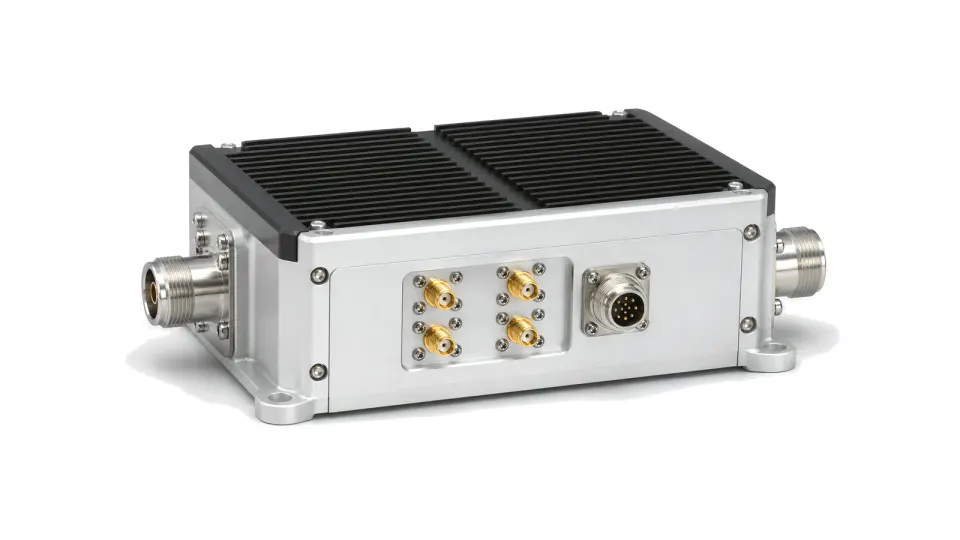
When should an RF transverter replace separate frequency converters?
Use an RF transverter when one assembly must translate both transmit and receive paths between a radio-side band and a target RF or microwave band while preserving duplexing, gain, noise, output level, isolation and control behavior. This family covers paired or bidirectional band-translation assemblies and external band-extension units. Discrete mixers and one-way upconverter or downconverter modules remain in their own categories.
Lock the frequency plan in both directions
Map every port and state: radio-side TX and RX bands, target-side bands, any IF, LO frequency and injection side, spectral inversion, wanted sideband, image location and T/R or duplex control. Define whether the LO and reference are internal or external, their accuracy and phase-noise limits, startup and settling time, coherence needs and behavior after reference loss.
Close receive and transmit budgets separately
For receive, review conversion gain or loss, noise figure, input compression, IIP3, blocker tolerance, image rejection, spurious responses and LO leakage. For transmit, review required drive, output power, gain control, compression and intermodulation, harmonics, unwanted sideband and carrier or LO feedthrough. Then verify TX-to-RX, LO-to-RF and port-to-port isolation in every operating state.
Verify the complete operating assembly
Set reference planes, impedance, filters or duplexer, control interface, supply sequence, calibration, thermal path and fault states before test. Measure desired transfer and a frequency-planned spur matrix for every direction and switch state across temperature and supply. Include mismatch, blockers, reference interruption and switching transients where the installed radio can encounter them.
- radio-side and target-side TX/RX bands and bandwidths
- LO plan, reference source, injection side, inversion and coherence
- receive gain, noise figure, compression, blockers, image and spurs
- transmit drive, output, linearity, harmonics, sideband and leakage
- duplex method, switching time, isolation and state truth table
- RF/IF interfaces, controls, power, thermal limits and acceptance conditions
Installed acceptance boundary
Approve the transverter with the actual radio, reference, filters or duplexer, cables, load and control timing represented. A single conversion-gain trace does not prove two-way spectral cleanliness, isolation, switching behavior or stability at the installed reference planes.