
What makes an RF phase shifter accurate in a real signal path?
An RF phase shifter is accurate only when commanded phase remains within error limits across frequency, state or control voltage, temperature and power while insertion loss, return loss and amplitude variation stay compatible with the signal-chain budget. A nominal 360-degree range or bit count does not establish that performance.
Define phase coverage at the system reference plane
Start with the required differential phase relative to a declared reference state and plane. Digital units need bit count, least-significant step, state coding and usable monotonic coverage; analog units need control range, transfer curve, monotonicity and hysteresis. Include any phase wrap or dead zone so the requested range represents calibrated system phase rather than an isolated device claim.
Separate phase accuracy from amplitude consistency
Review RMS and peak phase error over every state, frequency and temperature, not only typical error at band center. Insertion loss, loss flatness and state-to-state amplitude error must be assessed at the same points because a correct phase with unequal amplitude still degrades beam shape, cancellation depth or vector modulation. Return loss should remain acceptable in all commanded conditions.
Match topology and interface to the operating task
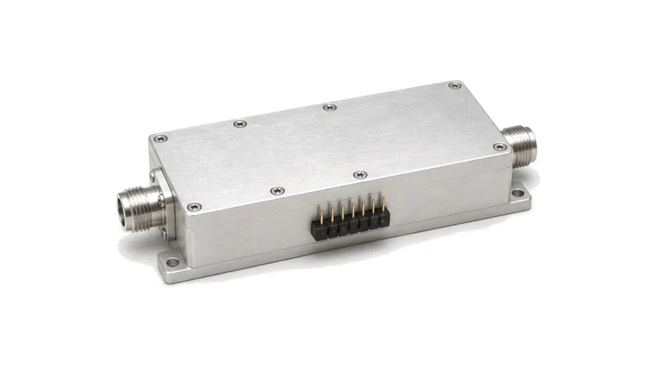
Switched-line, loaded-line, reflective, vector and continuously variable designs trade bandwidth, loss, resolution, power and control complexity differently. A connectorized or drop-in module adds transitions, bias conditioning, shielding and mechanical interfaces that may improve integration but change the reference plane. Specify RF connectors, directionality, control connector, supply and fail-state behavior.
Check power, linearity and hot-switching conditions
State input compression, third-order intercept, peak and average power, pulse width and duty cycle at temperature. If phase can change while RF is present, require hot-switching limits, transient amplitude and phase, settling time and repetitive switching life. High reflected power or poor load match can raise internal voltage beyond what forward-power ratings imply.
Plan calibration and acceptance before procurement
Use a vector network analyzer with stable cables, a defined reference state and de-embedded fixture or adapters. Sweep every digital state or enough analog control points to resolve the transfer curve, recording phase, insertion loss and return loss versus frequency. Repeat at temperature and relevant power, then derive RMS and worst-case errors using the same phase-unwrapping and reference convention used by the system calibration.
Specify repeatability, drift and control timing
For arrays and coherent channels, cycle-to-cycle phase repeatability and matched tracking can matter more than a one-time room-temperature value. State logic levels, control polarity, current, update rate, latency, glitch energy, enable behavior and power-up state. Define whether factory data, unit calibration tables or temperature compensation coefficients must accompany each serial number.
RFQ data required for an RF phase shifter
- Frequency band and reference impedance
- Required phase range and reference state
- Digital bits and coding or analog control law
- RMS and peak phase-error limits
- Insertion loss and state amplitude error
- Return loss in every state
- Input power, pulse and duty cycle
- Compression, linearity and reflected-power condition
- Switching time, transient and hot-switching need
- Temperature, environment and lifetime
- RF, DC and control interfaces
- Calibration files and acceptance method
Category boundary
This category covers complete packaged, drop-in, connectorized, coaxial or waveguide RF phase-shifting devices and modules. It excludes phase-shifter ICs or bare die, fixed phase-matched cable sets, standalone line stretchers and complete beamformer or antenna assemblies unless those items are used to define the module-level requirement.