
LCRF

Privacy preferences

Choose optional purposes independently. You can change or withdraw your choice at any time from the footer.

Strictly necessary

Required for security, session functions and storing your privacy choice.

Always active
Preferences

Remembers optional display or language settings when these features are enabled.

Analytics

Uses first-party visitor and session identifiers to measure pages, referrals and inquiry interactions.

Marketing

Allows marketing measurement or third-party advertising technologies if they are introduced in the future.

Bi-directional Couplers

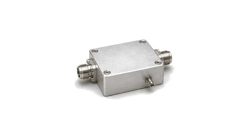
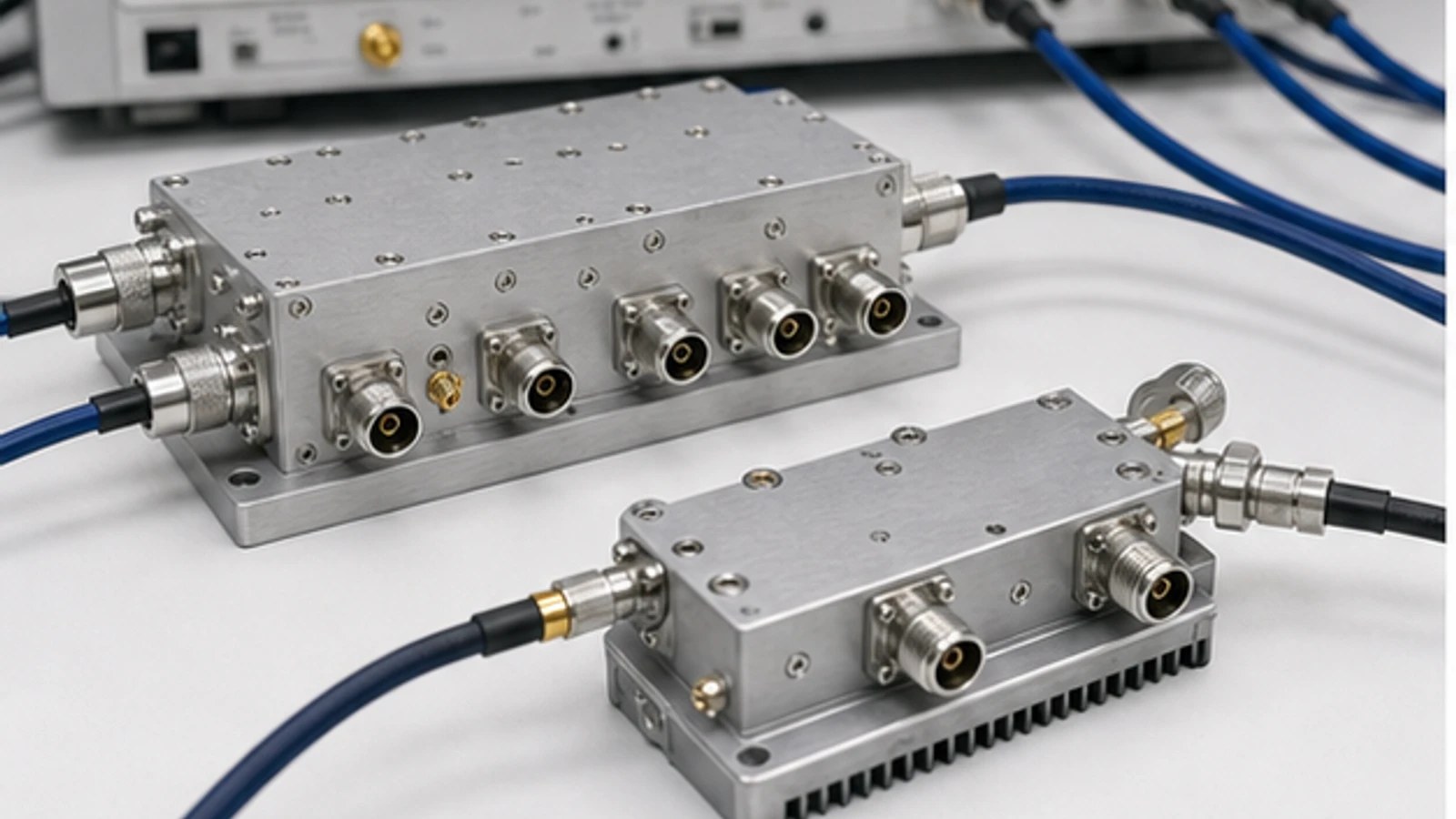
Bi-directional couplers sample forward and reverse RF power in the same transmission path, usually through separate coupled ports. They are used when delivered and reflected power must be monitored together in amplifiers, antenna feeds and RF tests.

Bi-directional Couplers

Articles

FAQ

What is the difference between an RF power divider and a directional coupler?

A divider creates two or more controlled output paths, while a directional coupler samples a defined fraction of a travelling wave and preserves a main through path.

How do coupling factor, directivity and return loss affect forward and reflected-power accuracy?

Coupling factor sets the sampled level, directivity limits separation of forward and reverse waves, and return loss determines how strongly the coupler and its interfaces disturb or re-reflect the signal. Detector accuracy alone cannot define the accuracy of a forward/reflected-power measurement.

Engineering inquiry

Share your RF requirement

Share the product, operating requirements and project context. Our engineering team will route your request to the right specialist.

AttachmentsAttach drawings, BOMs, specifications or test files. Up to 5 files, 10 MB each and 25 MB total.
or drag and dropPDF, DOCX, XLSX, CSV, TXT, JPG, PNG, S1P and S2P
Typically reviewed within one business dayProject information is handled confidentially

Bi-directional Couplers

A bi-directional coupler measures energy travelling in both directions on an RF line. It provides separate information for forward and reflected power so the system can observe delivered power and load mismatch from the same installed component.

System role

These couplers are used in power amplifier protection, antenna matching checks, transmitter telemetry, load monitoring and RF benches that need both forward and reverse readings.

Engineering factors

  • Forward and reverse coupling values must remain predictable over the operating band.
  • Directivity separates the sampled waves and affects reflected-power accuracy.
  • Insertion loss, isolation, power rating and connector format define the through path limits.