
LCRF

Privacy preferences

Choose optional purposes independently. You can change or withdraw your choice at any time from the footer.

Strictly necessary

Required for security, session functions and storing your privacy choice.

Always active
Preferences

Remembers optional display or language settings when these features are enabled.

Analytics

Uses first-party visitor and session identifiers to measure pages, referrals and inquiry interactions.

Marketing

Allows marketing measurement or third-party advertising technologies if they are introduced in the future.

Power Dividers

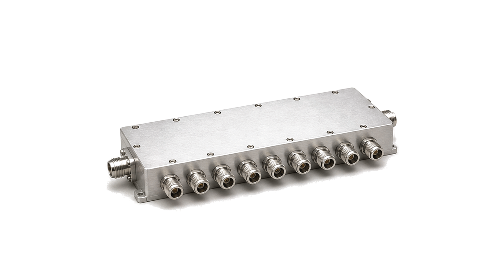
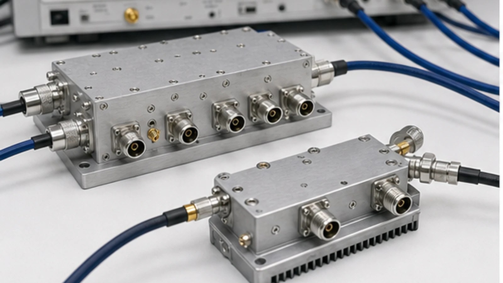
RF power dividers split one input into two or more controlled output paths for test benches, antenna feeds and multichannel RF systems. Key factors include split ratio, insertion loss, balance, isolation and power rating.

Power Dividers

Articles

FAQ

How do split loss and excess insertion loss differ in an RF power divider?

Split loss is the unavoidable 10 log10(N) dB reduction when input power is divided among N equal outputs; excess loss is additional real-device loss beyond that ideal split.

When should Wilkinson, resistive, 90-degree or 180-degree RF networks be used?

Choose by the required phase relationship, bandwidth, loss and isolation rather than by port count alone. A Wilkinson network is the usual starting point for equal 0-degree split or combine paths with useful output isolation and low excess loss over its designed band.

What is the difference between an RF power divider and a directional coupler?

A divider creates two or more controlled output paths, while a directional coupler samples a defined fraction of a travelling wave and preserves a main through path.

Can an RF power divider be used as a combiner?

Often yes, but only when the divider is reciprocal, the manufacturer permits reverse use, and the input signals meet the required amplitude, phase and power conditions. A 0-degree divider used in reverse produces the vector sum at the common port; it does not simply add two headline power ratings.

Engineering inquiry

Share your RF requirement

Share the product, operating requirements and project context. Our engineering team will route your request to the right specialist.

AttachmentsAttach drawings, BOMs, specifications or test files. Up to 5 files, 10 MB each and 25 MB total.
or drag and dropPDF, DOCX, XLSX, CSV, TXT, JPG, PNG, S1P and S2P
Typically reviewed within one business dayProject information is handled confidentially

Power Dividers

Power dividers route a single RF or microwave input into multiple output paths while keeping the port relationship predictable. They are used when the same signal must feed several receivers, instruments, antennas or parallel RF paths.

Signal-chain role

A divider normally sits between a source, driver, receiver front end, antenna feed or measurement point and the downstream branches that need a common reference or signal.

Engineering factors

  • Split ratio and port count define how the input power is shared.
  • Insertion loss, return loss, isolation and amplitude or phase balance affect measurement repeatability and channel matching.
  • Power rating, connector type, impedance and mechanical format set the practical integration limits.