
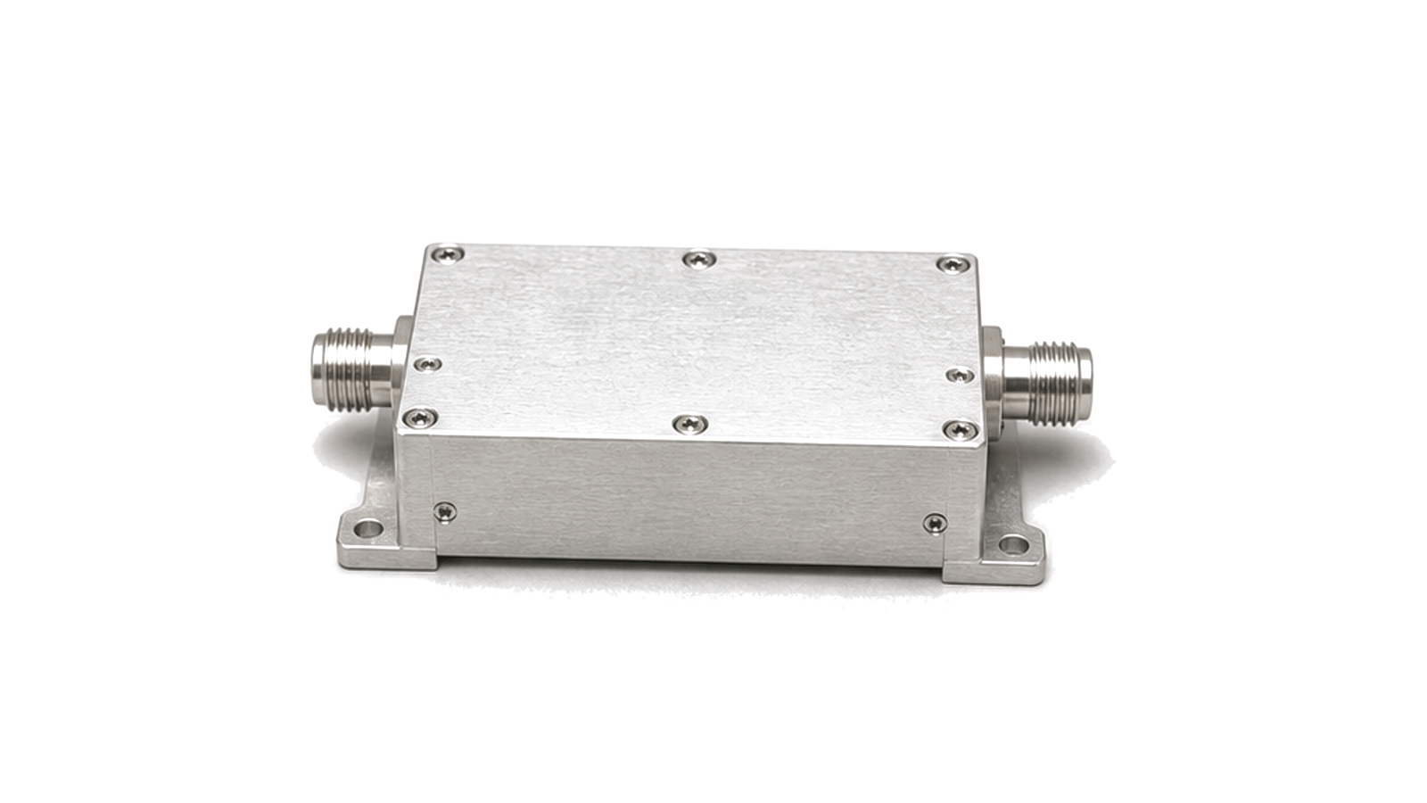
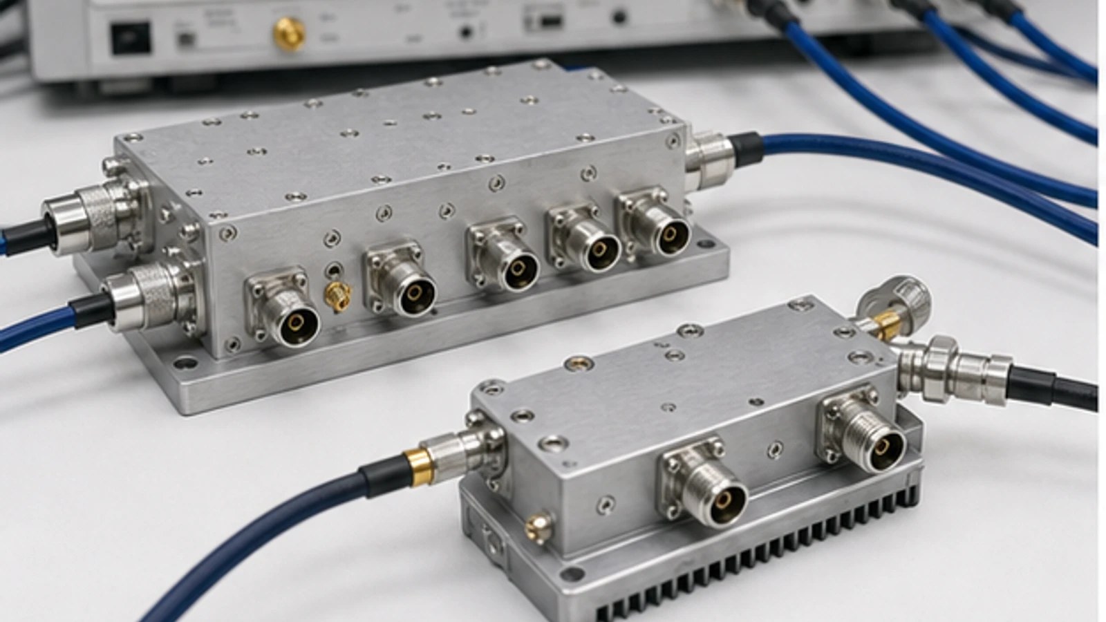
What must be specified when selecting a 180° hybrid coupler?
Define the sum, difference and collinear port convention first, then compare amplitude balance, phase error from 180°, isolation, return loss, excess loss and power over the complete operating band with every unused port correctly terminated. A 180° hybrid is a reciprocal four-port network. Exciting its sum port produces equal in-phase outputs, while exciting its difference port produces equal outputs with nominal 180° separation; used in reverse, those ports form the vector sum and difference of two input signals. Port names are not interchangeable between drawings, so a block diagram and the manufacturer's S-parameter reference planes must accompany the part number. A three-port balun may create differential outputs but does not provide the isolated fourth port of a hybrid.
Start with the vector function and port map
State whether the device will divide one source, combine two amplifiers, form sum and difference channels, feed a balanced mixer or cancel a common-mode component. Record which physical connector is Σ, Δ and each collinear arm, the required relative polarity, impedance and signal direction. In combiner service, equal in-phase inputs add at Σ and cancel at Δ; equal anti-phase inputs do the reverse. Any amplitude or phase mismatch sends power toward both result ports, so the isolated or difference-side termination must be rated for credible fault and imbalance energy rather than treated as an unused connector.
Compare balance, isolation and bandwidth together
Use amplitude imbalance and phase deviation from the ideal 180° across the actual band, not a single centre-frequency value. Add return loss at all ports, isolation between the collinear arms, insertion or excess loss and group-delay or phase tracking when the application is cancellation-sensitive. Rat-race structures are often compact and useful around a designed band but can be narrower than multisection coupled-line or magic-tee implementations. Connector transitions, substrate launches, enclosure modes and termination quality can dominate measured performance. For high power, include average and peak limits, voltage standing wave, thermal path, isolated-load dissipation and mismatch behavior.
Verify the full four-port network at the project reference planes
Measure a calibrated four-port S-parameter set when possible; otherwise keep every unmeasured port in a verified matched load and preserve cable phase between swaps. De-embed fixtures to the agreed reference planes, unwrap phase consistently and calculate amplitude and phase balance from the two relevant transfer paths. Check isolation and return loss with the specified termination, then repeat critical points at temperature and drive level. In combiner tests, apply controlled amplitude and phase errors and confirm where the rejected power goes. Reject a device whose headline 180° value is met only at one frequency, whose port map is ambiguous, or whose isolated load cannot survive the expected imbalance.
- Σ, Δ and collinear-port map, signal direction and reference planes
- Operating band and required in-phase or anti-phase function
- Amplitude imbalance and phase error across the complete band
- Isolation, return loss, insertion or excess loss and delay tracking
- Average and peak power, mismatch, thermal path and isolated-load rating
- Four-port S-parameter method, terminations, fixture removal and acceptance limits
Category boundary
This category covers reciprocal four-port 180° hybrids, including rat-race, magic-tee and coupled-line implementations used for equal in-phase or differential splitting and sum/difference combining. Three-port baluns and transformers, 90° quadrature hybrids, Wilkinson power dividers, unequal directional couplers and resistive splitters are separate categories because their port isolation, phase relationship and termination behavior differ.