
What must a waveguide orthomode transducer specification prove?
It must prove that the common dual-mode port separates or combines two declared orthogonal linear polarizations with controlled loss, match, isolation and polarization purity across the full operating band at the delivered mechanical reference planes. A three-port drawing alone does not prove useful mode separation.
Freeze the polarization basis and port geometry
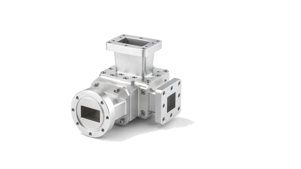
Define the common port as circular, square or another dual-mode guide, identify the supported dominant modes, and state the two single-mode output guides, flange standards, clocking and viewing convention. Mark horizontal and vertical orientation on the mechanical drawing. If circular polarization is required, identify the separate polarizer and its handedness; an OMT separates orthogonal linear modes and is not automatically a circular polarizer.
Compare both polarization paths, not one headline value
Request insertion loss and return loss for the common-to-through and common-to-side paths at band edges and representative points. Add isolation between the rectangular ports, cross-polarization discrimination, amplitude balance, differential phase or electrical length and group delay where a coherent receiver or beamforming network uses both channels. Limits should apply after the specified bends, twists, transitions or adapters when those parts are delivered with the assembly.
Control higher-order modes and manufacturing asymmetry
Common circular or square guide can support unwanted modes above cutoff. Specify the usable band, mode purity, transition length and the allowed discontinuities near the common aperture. Split-block alignment, probe position, septum geometry, flange flatness, surface finish and plating can unbalance the two paths and reduce isolation. Thermal cycling, vibration, pressure or vacuum interfaces and material pairing belong in the requirement when the OMT is part of a sealed feed chain.
Set power and environmental boundaries
Declare continuous or pulsed power for each polarization, simultaneous-port operation, peak electric-field concern, pressurization, multipactor screening or passive intermodulation where relevant. Include reflected power from the antenna or downstream network. A low small-signal insertion loss does not establish high-power capability; the design, joint current paths, sharp features, finish, thermal path and test atmosphere determine the safe envelope.
Measure a complete multiport response
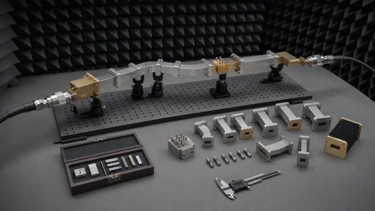
Calibrate a vector network analyzer to the delivered reference planes with suitable waveguide standards and mode-controlled fixtures. Measure reflection at all ports, transmission for each polarization path, output-port isolation, cross-coupled response, phase balance and repeatability after reconnection. Terminate unused ports correctly and preserve port orientation. For antenna-feed acceptance, add a radiated co- and cross-polar measurement because network isolation alone does not prove the installed feed pattern.
Make acceptance data reproducible
Require S-parameter files with port definitions, frequency points, calibration method, fixture treatment, temperature and uncertainty. Record mechanical drawings, flange and clocking references, materials, plating and torque. Repeat selected band-edge and isolation points after environmental exposure or disassembly. Reject data that mixes reference planes, reports only a center-frequency result or omits one polarization path.
RFQ data for an orthomode transducer
- Operating band and waveguide sizes
- Common-port shape and supported modes
- Output-port flanges, orientation and clocking
- Insertion and return loss for both paths
- Port isolation and cross-polarization discrimination
- Amplitude, phase and group-delay balance
- CW or pulsed power and simultaneous-port operation
- Pressure, vacuum, temperature, vibration and finish
- Delivered bends, twists, adapters or polarizer
- VNA and radiated acceptance reference planes
Category boundary
This category covers passive reciprocal waveguide junctions that separate or combine two orthogonal linear polarization modes between one common dual-mode port and two single-mode ports. Standalone polarizers, duplexers, magic tees, hybrids, feed horns, antennas, receivers, transmitters and complete feed assemblies remain separate unless they are explicitly supplied and tested as part of the OMT assembly.
Control the complete path, not a list of nominally compatible parts
- Waveguide Orthomode Transducers supplier / Waveguide Orthomode Transducers manufacturer
- Close acceptance with dimensional, RF and configuration evidence The acceptance package should identify every part and serial, material and finish, controlled drawing revision, flange and aperture inspection, assembly orientation, support configuration, calibration and instrument state, environmental condition, raw complex data, corrected result, uncertainty and pass limits....
- Waveguide Orthomode Transducers technical specifications
- Freeze band, mode and every discontinuity before selecting hardware Start with the continuous operating band, verification band and any guard band rather than a center frequency. Name the waveguide designation and internal aperture, intended dominant mode, polarization and propagation direction....
- Waveguide Orthomode Transducers selection guide
- Freeze band, mode and every discontinuity before selecting hardware Start with the continuous operating band, verification band and any guard band rather than a center frequency. Name the waveguide designation and internal aperture, intended dominant mode, polarization and propagation direction....
- Waveguide Orthomode Transducers test and verification
- Make calibration standards, reference planes and uncertainty part of the design Choose a VNA calibration method and standard set that match the waveguide band, port topology and insertability. Record standard definitions, dimensions, line or offset values, kit identity, temperature and certificate status....
How to Specify and Verify Waveguide and Millimeter-Wave Hardware
Turn a waveguide path into a reviewable specification by controlling band and mode, aperture and flange interfaces, loss and phase, peak and average power, mechanical tolerances, calibration reference planes, uncertainty and acceptance evidence.