
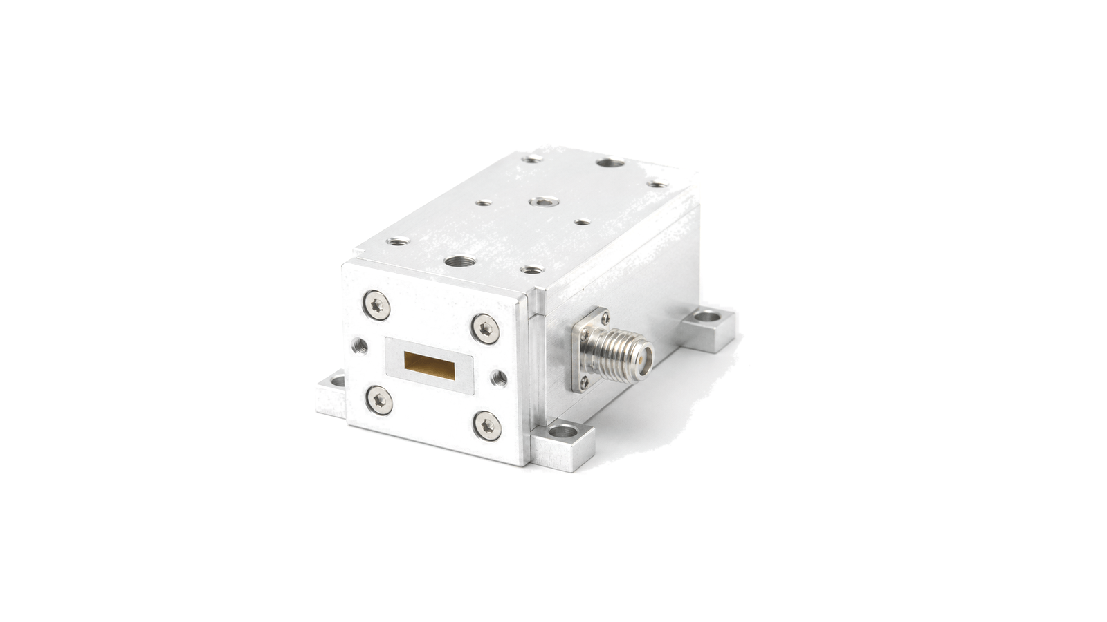
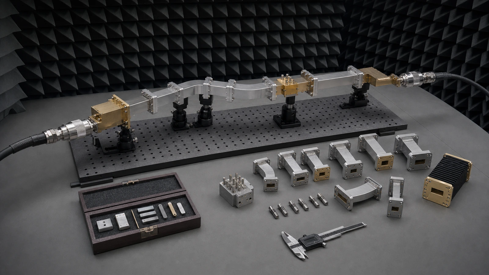
Millimeter-Wave Modules
Bias and thermal design set the reliability margin. Millimeter-Wave Modules handles microwave or millimeter-wave energy through precision metal structures for radar, satellite, laboratory and high-frequency communication hardware. The information is organized around how this hardware is used in an RF system.
Key data centers on waveguide band, flange interface, loss, VSWR, power rating and alignment. Those details help engineering, sourcing and integration teams compare the record against the actual signal path, mechanical boundary and operating environment.
When reviewed with model data, outline dimensions, test conditions and delivery documents, the content makes project scope, constraints and follow-up verification points easier to align early.
Control the complete path, not a list of nominally compatible parts
- Millimeter-Wave Modules supplier / Millimeter-Wave Modules manufacturer
- Close acceptance with dimensional, RF and configuration evidence The acceptance package should identify every part and serial, material and finish, controlled drawing revision, flange and aperture inspection, assembly orientation, support configuration, calibration and instrument state, environmental condition, raw complex data, corrected result, uncertainty and pass limits....
- Millimeter-Wave Modules technical specifications
- Freeze band, mode and every discontinuity before selecting hardware Start with the continuous operating band, verification band and any guard band rather than a center frequency. Name the waveguide designation and internal aperture, intended dominant mode, polarization and propagation direction....
- Millimeter-Wave Modules selection guide
- Freeze band, mode and every discontinuity before selecting hardware Start with the continuous operating band, verification band and any guard band rather than a center frequency. Name the waveguide designation and internal aperture, intended dominant mode, polarization and propagation direction....
- Millimeter-Wave Modules test and verification
- Make calibration standards, reference planes and uncertainty part of the design Choose a VNA calibration method and standard set that match the waveguide band, port topology and insertability. Record standard definitions, dimensions, line or offset values, kit identity, temperature and certificate status....
How to Specify and Verify Waveguide and Millimeter-Wave Hardware
Turn a waveguide path into a reviewable specification by controlling band and mode, aperture and flange interfaces, loss and phase, peak and average power, mechanical tolerances, calibration reference planes, uncertainty and acceptance evidence.