
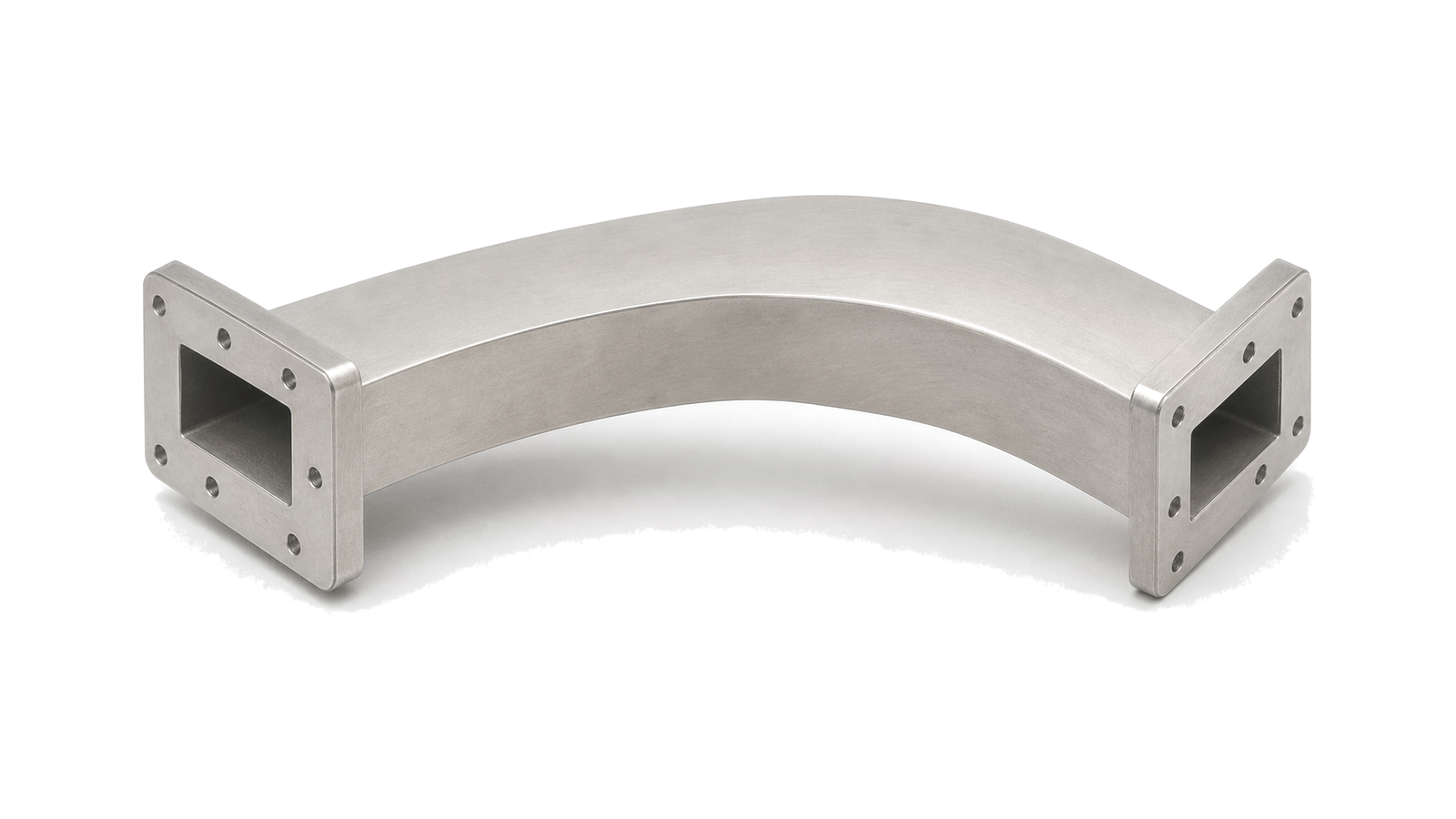
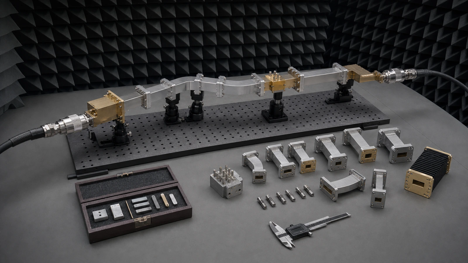
Waveguide Bends and Twists
Waveguide bends and twists route microwave energy through constrained mechanical paths while changing direction or orientation of the guide. They are used in antenna feeds, racks and compact assemblies where the waveguide path must fit the enclosure.
Routing and orientation
Bends change the physical route of a waveguide run; twists rotate the guide orientation so the path can mate with another flange or assembly without redesigning the surrounding hardware.
Relevant data
Useful data includes operating band, bend angle or radius, twist angle, flange standard, insertion loss, VSWR, power handling, material and installed envelope.
Control the complete path, not a list of nominally compatible parts
- Waveguide Bends and Twists supplier / Waveguide Bends and Twists manufacturer
- Close acceptance with dimensional, RF and configuration evidence The acceptance package should identify every part and serial, material and finish, controlled drawing revision, flange and aperture inspection, assembly orientation, support configuration, calibration and instrument state, environmental condition, raw complex data, corrected result, uncertainty and pass limits....
- Waveguide Bends and Twists technical specifications
- Freeze band, mode and every discontinuity before selecting hardware Start with the continuous operating band, verification band and any guard band rather than a center frequency. Name the waveguide designation and internal aperture, intended dominant mode, polarization and propagation direction....
- Waveguide Bends and Twists selection guide
- Freeze band, mode and every discontinuity before selecting hardware Start with the continuous operating band, verification band and any guard band rather than a center frequency. Name the waveguide designation and internal aperture, intended dominant mode, polarization and propagation direction....
- Waveguide Bends and Twists test and verification
- Make calibration standards, reference planes and uncertainty part of the design Choose a VNA calibration method and standard set that match the waveguide band, port topology and insertability. Record standard definitions, dimensions, line or offset values, kit identity, temperature and certificate status....
How to Specify and Verify Waveguide and Millimeter-Wave Hardware
Turn a waveguide path into a reviewable specification by controlling band and mode, aperture and flange interfaces, loss and phase, peak and average power, mechanical tolerances, calibration reference planes, uncertainty and acceptance evidence.