
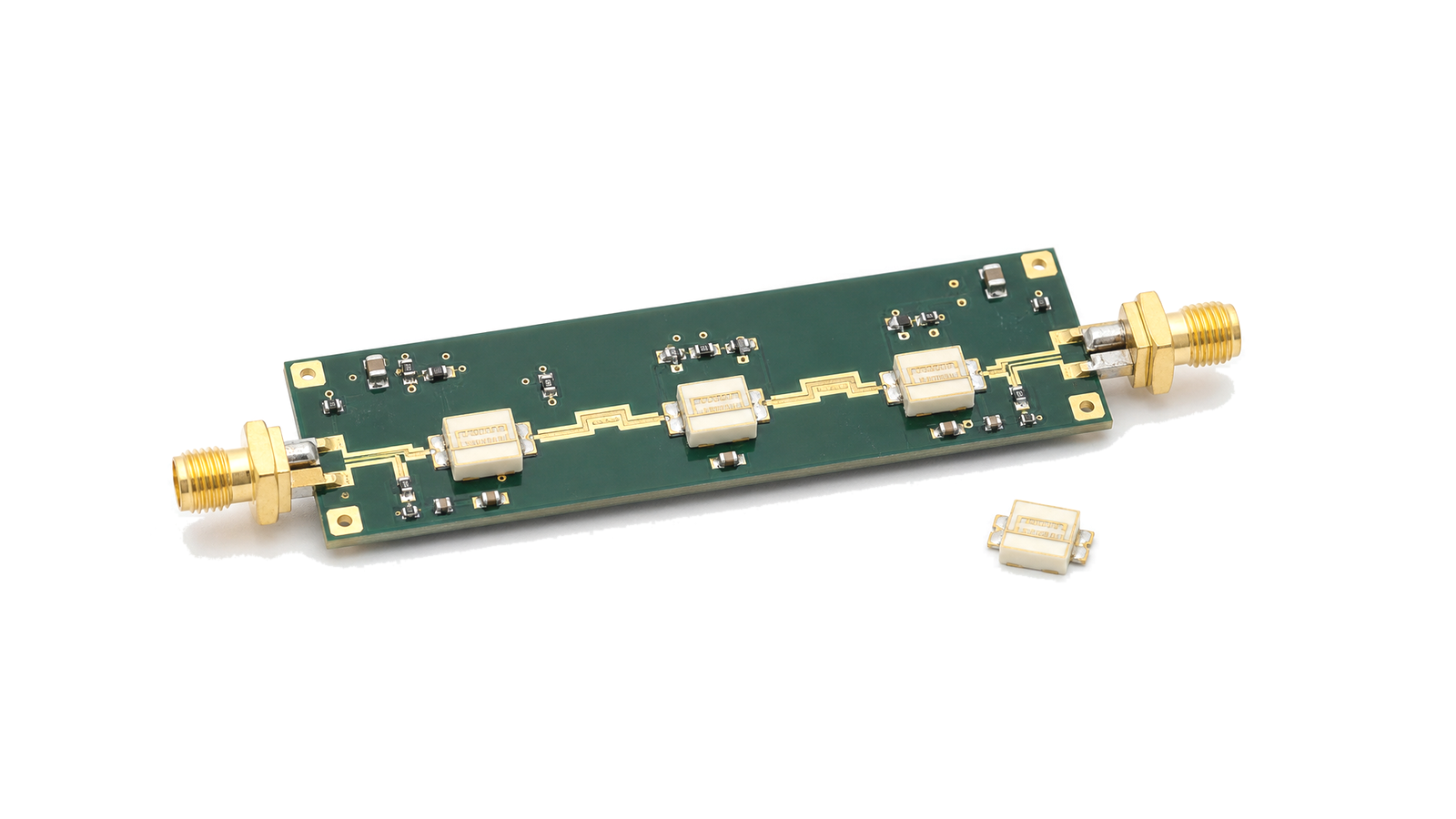
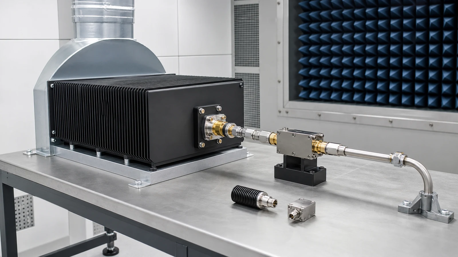
RF equalizers for response correction
RF equalizers introduce a controlled amplitude slope across frequency so a wider RF path can remain closer to the intended response. They are used where coaxial cable loss, amplifier gain tilt or fixture response changes the signal level across the operating band.
Typical data points
Common datasheet fields include operating bandwidth, equalization slope, insertion loss, return loss, impedance, connector type, package format, power rating and temperature range.
What does the RF Equalizers category cover?
RF equalizers compensate frequency-dependent loss or gain tilt in RF and microwave paths, helping cable runs, amplifier chains and test fixtures maintain a more controlled amplitude response.
How should hardware in the RF Equalizers category be selected?
A practical method for specifying passive RF loads, terminations and impedance networks by function, reference plane, complex impedance, reflection, insertion loss, waveform power, thermal derating, environment and acceptance evidence.
- Define the electrical and thermal boundary before choosing the hardware
- Classify the passive function before selecting a component
- Freeze frequency, characteristic impedance and the reference plane
Which specifications matter when evaluating RF Equalizers?
Common datasheet fields include operating bandwidth, equalization slope, insertion loss, return loss, impedance, connector type, package format, power rating and temperature range.
How should hardware in the RF Equalizers category be tested and verified?
Specify a passive RF network or load by first naming its function and calibrated reference plane. Freeze continuous frequency coverage, characteristic impedance, port state, return loss or VSWR, insertion response, average and peak power, pulse width, duty cycle, mismatch or reverse power, mounting temperature, cooling, connector and environment. Then define VNA calibration, power-stress conditions, thermal stabilization, pass/fail limits and retained data.