
What belongs in the RF absorber category?
RF absorbers are lossy electromagnetic materials used to reduce a defined reflection, cavity mode, near-field coupling path or free-space echo over stated frequencies and installation conditions. Choose the physical form only after the unwanted field path and acceptance measurement are known. A chamber pyramid, ferrite tile, thin elastomer sheet and molded cavity insert can all be called an absorber, but their thickness, backing, incidence response, power handling and mounting evidence are not interchangeable.
Match material form to the field problem
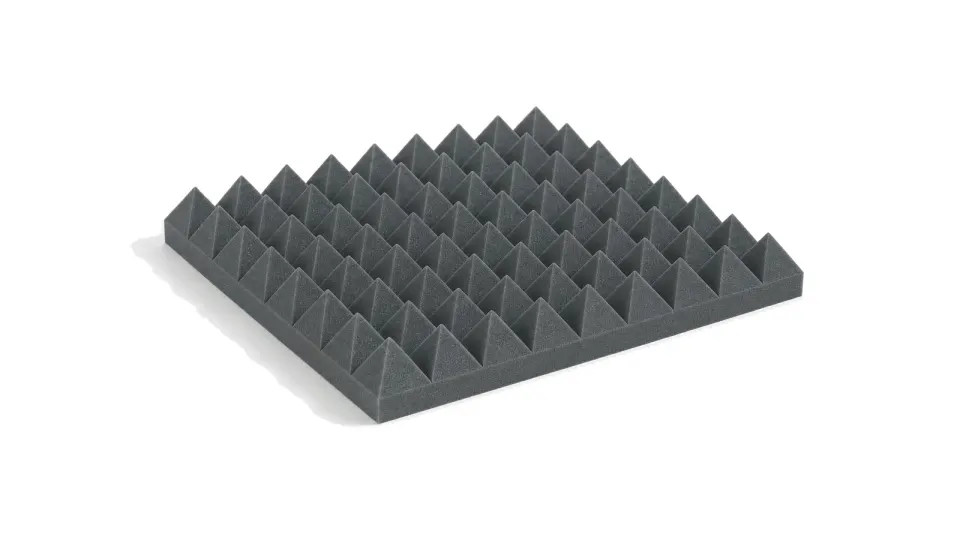
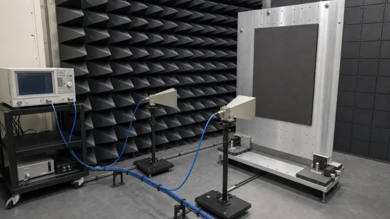
Carbon-loaded foam and pyramidal forms create a gradual transition from free space and are commonly evaluated by free-space reflectivity. Ferrite tile and hybrid constructions can extend low-frequency treatment where room depth is limited. Thin flexible sheets and molded pieces are useful inside housings, around apertures or near resonant structures, but their performance depends strongly on metal backing, compression, adhesive and local field orientation.
State whether the task is chamber treatment, enclosure resonance damping, antenna-coupling reduction, cable or lid leakage control, or a calibrated radiometric target. The same material can produce a different result when incidence angle, polarization, backing gap, edge treatment or nearby metal changes. Coupon data screens candidates; the installed assembly closes the decision.
Compare evidence, not product names
| Selection boundary | Evidence to request | Do not accept |
|---|---|---|
| Electromagnetic task | Target band, field location, incidence, polarization and required reduction | A generic 'broadband absorber' claim |
| Material assembly | Form, thickness, density, metal backing, adhesive, seams and compression | Coupon data without the installed stack |
| RF performance | Reflectivity or transmission method, reference standard, geometry, uncertainty and full curve | A single dB value measured without a stated setup |
| Power and heat | CW or pulsed power density, hot-spot location, airflow and service temperature | A power number without duration or cooling |
| Environment | Humidity, chemicals, flame, vacuum/outgassing and aging evidence as applicable | A material designation used as qualification |
Information needed before an RF absorber can be selected
- Frequency intervals, unwanted mode or reflection path and target reduction
- Available depth, area, mass, backing metal and mechanical keep-out
- Incidence-angle and polarization range or local E/H-field orientation
- Average and peak field or power density, duty cycle and hot-spot duration
- Temperature, airflow, moisture, chemical, flame and vacuum constraints
- Adhesive, fastener, seam, edge, gap and compression requirements
- Coupon test, free-space test, chamber mapping or installed before/after acceptance method
Category boundary
This category includes RF and microwave absorber foam, sheet, tile and shaped parts whose primary function is to convert electromagnetic energy into loss. Conductive shielding gaskets, metal enclosures, thermal pads, ferrite circuit components and complete anechoic chambers remain separate entities even when they are used beside absorber material.