
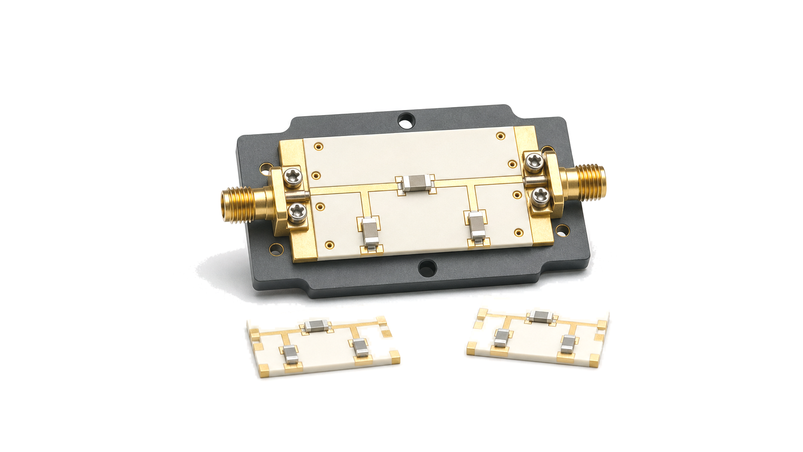
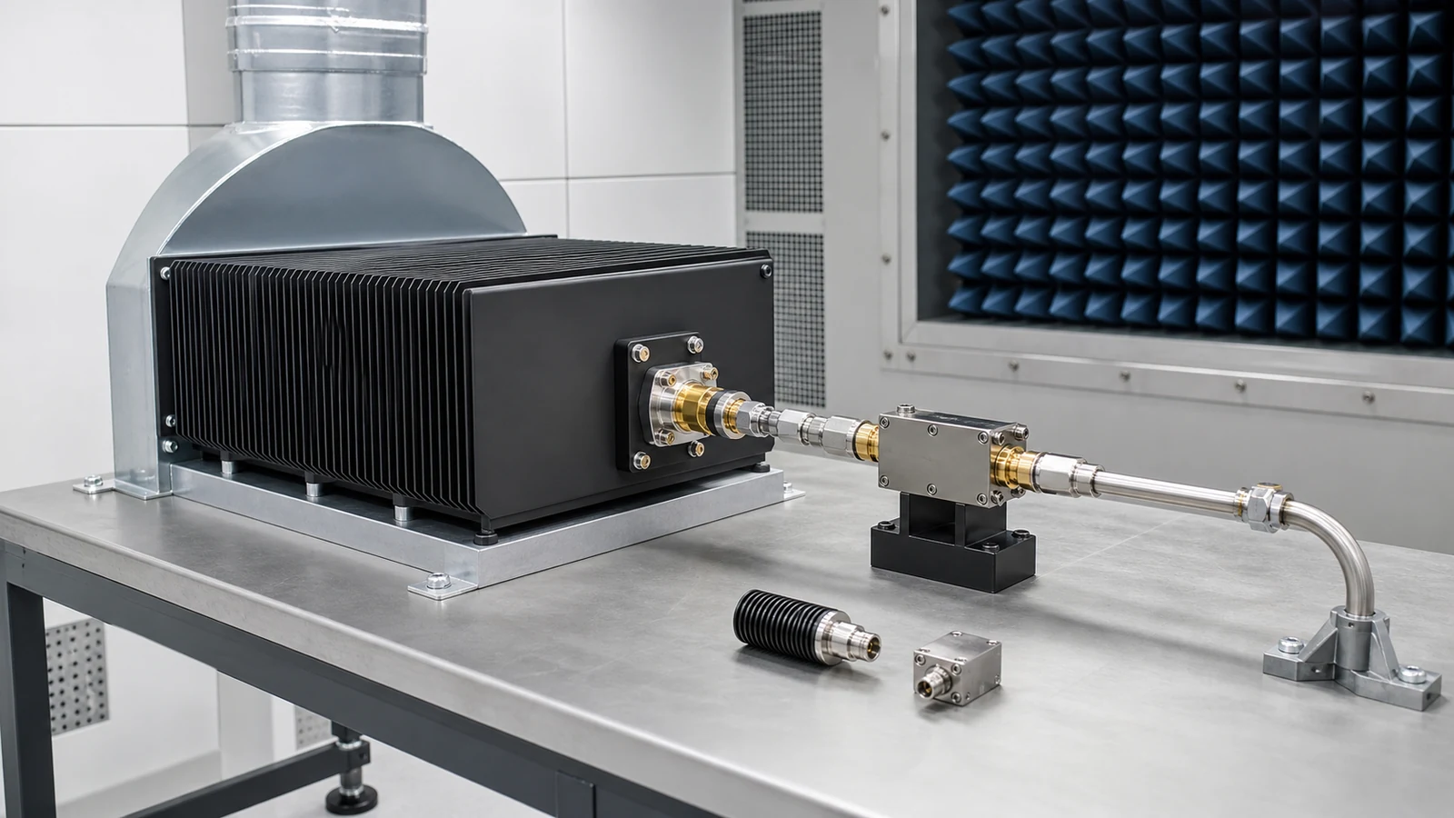
RF matching pads
Matching pads are resistive RF components placed between two ports when a small amount of loss is acceptable in exchange for a more stable match. They can reduce the effect of load mismatch, improve return loss and protect measurement or receiver interfaces from reflected energy.
Typical data points
Common fields include nominal impedance, attenuation value, frequency range, return loss, insertion loss tolerance, power rating, connector interface, package format and temperature range.
What does the RF Matching Pads category cover?
RF matching pads add controlled attenuation between ports to improve match, reduce reflections and isolate sensitive RF instruments or modules from mismatch effects.
How should hardware in the RF Matching Pads category be selected?
A practical method for specifying passive RF loads, terminations and impedance networks by function, reference plane, complex impedance, reflection, insertion loss, waveform power, thermal derating, environment and acceptance evidence.
- Define the electrical and thermal boundary before choosing the hardware
- Classify the passive function before selecting a component
- Freeze frequency, characteristic impedance and the reference plane
Which specifications matter when evaluating RF Matching Pads?
Common fields include nominal impedance, attenuation value, frequency range, return loss, insertion loss tolerance, power rating, connector interface, package format and temperature range.
How should hardware in the RF Matching Pads category be tested and verified?
Specify a passive RF network or load by first naming its function and calibrated reference plane. Freeze continuous frequency coverage, characteristic impedance, port state, return loss or VSWR, insertion response, average and peak power, pulse width, duty cycle, mismatch or reverse power, mounting temperature, cooling, connector and environment. Then define VNA calibration, power-stress conditions, thermal stabilization, pass/fail limits and retained data.