
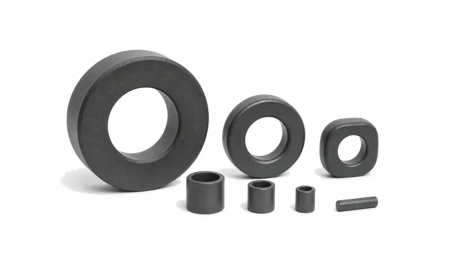
How should a ferrite RF device be selected for EMI suppression?
Locate the unwanted current and its frequency range first, then choose a ferrite whose resistive and reactive impedance remains useful under the actual current, temperature, conductor geometry and source-load impedances. A ferrite is not a universal noise blocker. Its complex permeability produces an impedance that changes with frequency: the inductive component can dominate in one region and the lossy resistive component in another. The same core can therefore suppress one conducted or radiated mechanism, have little effect on another, or create ringing when combined with circuit capacitance. Published impedance at one test frequency is only a checkpoint, not an installed attenuation value.
Identify the noise mode and the useful-signal boundary
Measure or estimate the frequencies and current path that cause the failure. Determine whether the unwanted current is common mode on a cable, differential mode between conductors, power-rail noise or a local high-frequency loop. Passing all conductors of a balanced path through one core primarily adds common-mode impedance; placing ferrite in only one conductor also affects differential current and the intended waveform. Record source and load impedance, signal bandwidth, allowable edge distortion or voltage drop, and the physical location where current is large enough for the ferrite to change the path.
Select material, geometry and current margin from full curves
Compare impedance magnitude together with its resistive R and reactive X components across the target band. Material mix sets the useful frequency region, while core dimensions and conductor turns set the magnetic path and impedance. Extra turns can increase low-frequency impedance but also add capacitance, leakage and winding limits. Check rated current, DC resistance for chip beads, ampere-turn bias, saturation or impedance derating, temperature range, self-heating, conductor insulation, core aperture and mechanical retention. Split cores add an unavoidable gap and may not reproduce a solid core's curve.
Verify suppression and side effects in the final path
Measure conducted current, insertion loss or radiated emissions before and after installation using the same reference configuration. Inspect the intended signal, supply droop, edge rate, ringing, startup and fault behavior as well as noise reduction. Repeat at maximum steady and transient current and at relevant temperature because bias and heating can reduce impedance. Move the core only as part of a controlled test: cable standing waves and source impedance can make placement decisive. Reject the choice if it merely shifts the emission peak, overheats, saturates, damages signal integrity or cannot be retained through vibration and service.
- Noise frequency range, measured current path and failure limit
- Common-mode, differential-mode, power-rail or local-loop mechanism
- Full |Z|, R and X curves rather than one nominal impedance point
- Material mix, core shape, aperture, conductor count and number of turns
- DC current, ampere-turn bias, temperature, heating and mechanical fit
- Installed noise reduction, waveform integrity and worst-case retest
Category boundary
This category covers ferrite beads, sleeves, solid and split cable cores, multi-hole cores and suppression plates whose primary task is frequency-selective loss or impedance around a conductor. Wound RF inductors and chokes, free-space absorber sheets and tiles, feedthrough filters, and complete ferrite circulators or isolators are separate categories with different reference planes and acceptance data.