
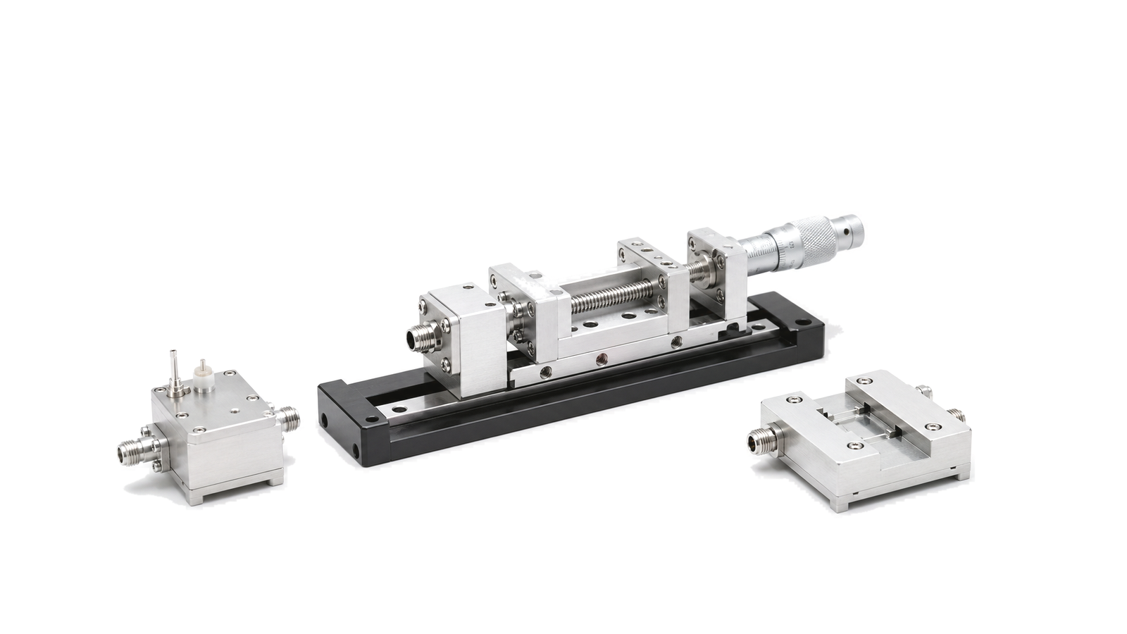
What defines a usable RF load-pull tuner setup?
A load-pull tuner setup is usable only when it presents the required source or load reflection coefficients at the declared DUT reference plane, survives the RF and bias conditions, and preserves calibrated power-wave measurements across the planned impedance, frequency, power and temperature sweep. Tuner VSWR at its own connector is not proof of gamma coverage at the device.
Start with the measurement objective and controlled terminals
State whether the work is source pull, load pull or simultaneous source-and-load control, and whether only the fundamental or selected harmonics must be controlled. Passive mechanical tuners offer robust power handling but lose achievable reflection coefficient through cable, fixture and probe loss. Active or hybrid systems can synthesize higher gamma and wider states when injection power, loop stability and isolation are sufficient. The architecture must follow the required output power, gain, efficiency, compression, AM/PM, IMD, EVM, ACPR or model-extraction result.
Specify gamma coverage at the DUT reference plane
Define frequency, impedance or reflection-coefficient region, phase resolution and state density at the actual device terminals. Loss between the tuner calibration plane and the DUT contracts the reachable Smith-chart area, especially near the chart edge. Include tuner-to-DUT spacing, adapters, bias tee, couplers, probes, fixture launches and de-embedding networks. Reject a proposal that quotes maximum tuner VSWR without a coverage map after these losses and at the required frequency and power.
Build calibration around every reference plane
Calibrate the VNA or vector receiver, power sensors, couplers and tuner using a traceable sequence that ends at the DUT planes. Characterize each tuner state versus frequency and include interpolation error, repeatability, connector reconnection and any fixture removal. If front-block components are added after tuner calibration, their S-parameters and orientation must be included. Retain raw calibrations, state files, de-embedding data and verification standards so the same impedance can be reconstructed later.
Protect the DUT while sweeping nonlinear states
Declare CW or pulsed operation, peak and average power, pulse width, duty cycle, drain and gate bias, sequencing, current limit, reflected-power limit and thermal control. High gamma can create voltage or current maxima that are not visible in a nominal 50-ohm test. Add directional detection, interlocks and fast shutdown for oscillation, overcurrent or excessive reverse power. Define excluded regions of the Smith chart when stability, tuner loss, injection power or DUT stress makes them unsafe.
Tie every contour to one controlled operating condition
Record frequency, available and delivered input power, output power, bias, temperature, fundamental and harmonic impedances, and the exact reference planes for every point. Gain, drain efficiency, PAE, compression and modulation metrics must not be mixed across different states. Use repeated anchor points to expose drift, backlash and thermal movement; report uncertainty and invalid points rather than smoothing them into favorable contours. Automation should preserve a complete state and calibration ledger.
Define the acceptance run before ordering accessories
Use a representative fixture or verification DUT to confirm impedance presentation, power-wave measurement and repeated positioning. Sweep enough states to cover the intended contour region, then repeat selected states after thermal soak and tuner travel. Acceptance should compare commanded and measured gamma at the DUT plane, delivered power, repeatability, settling time and protection behavior. Export formats must preserve complex impedance, conditions and validity flags for circuit design or model extraction.
RFQ data required for load-pull tuners and accessories
- Frequency range and connector or probe interface
- Source, load and harmonic-control scope
- Required gamma or impedance region at the DUT plane
- Passive, active or hybrid architecture
- CW/pulsed power, duty cycle and reflected power
- DUT bias, current limit and sequencing
- Fixture, bias tee, coupler and cable losses
- Calibration and de-embedding reference planes
- Metrics, modulation bandwidth and sweep variables
- State count, speed, repeatability and automation
- Thermal, stability and protection limits
- Calibration, state and result-file deliverables
Category boundary
This category covers impedance tuners, tuner calibration and verification hardware, low-loss interconnects, fixtures, bias networks, couplers, protection and control accessories used to present controlled source or load impedances. It excludes ordinary fixed 50-ohm loads, general-purpose VNAs or signal generators, and complete PA test benches unless those items define the accessory interface or calibration requirement.